Reflection type liquid crystal display apparatus and liquid crystal projector system
- Summary
- Abstract
- Description
- Claims
- Application Information
AI Technical Summary
Benefits of technology
Problems solved by technology
Method used
Image

Examples
embodiment 1
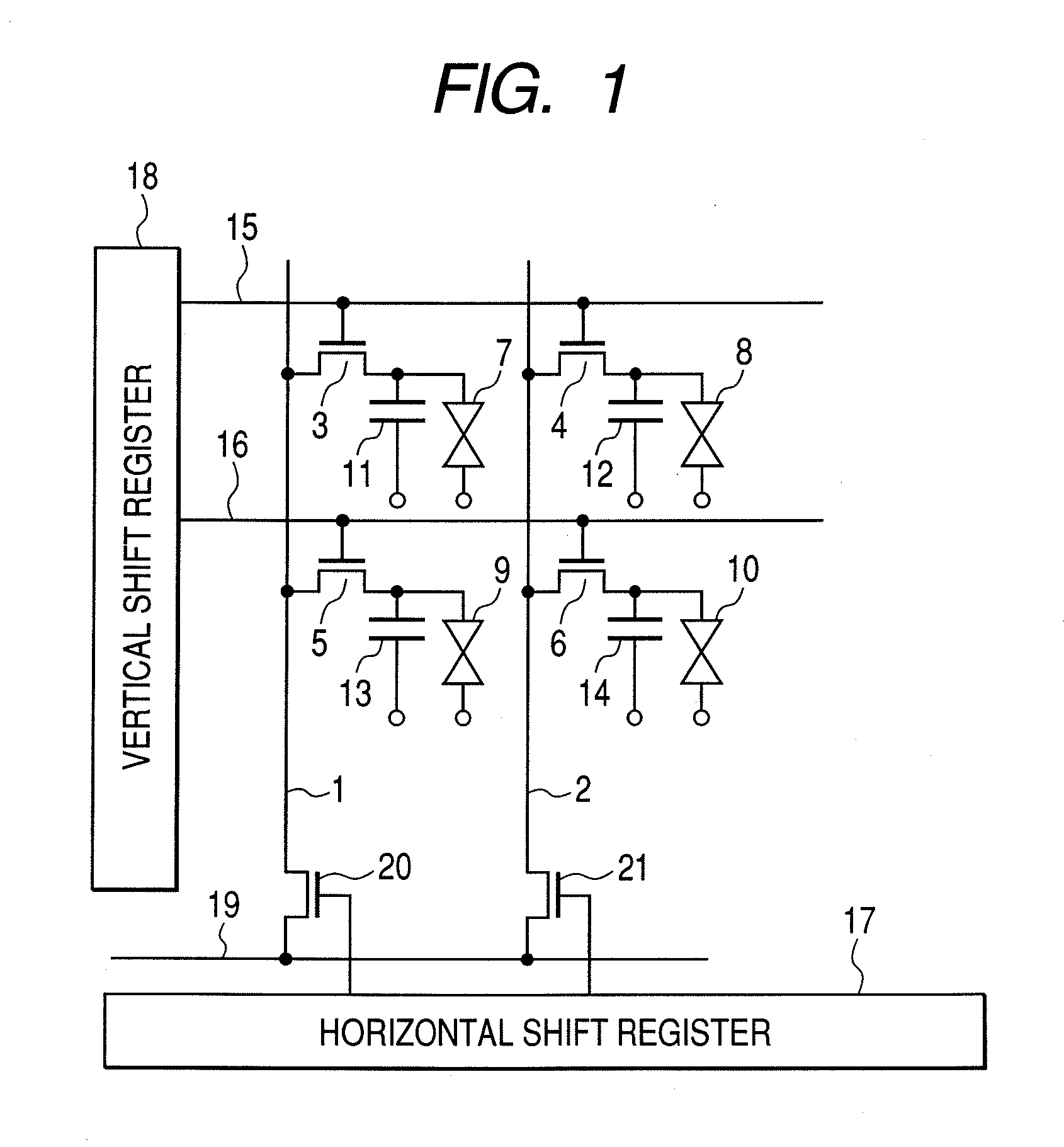
[0039]Now, Embodiment 1 of the present invention will be described in detail, based on FIG. 1. FIG. 1 is an equivalent circuit diagram illustrating a configuration of the reflection type liquid crystal display apparatus according to the present invention.
[0040]In FIG. 1, signal lines 1 and 2, transistors 3 to 6, that are switch elements of a pixel part, liquid crystals 7 to 10, holding capacitors 11 to 14, drive lines (scanning lines) 15 and 16, a horizontal shift register 17, and a vertical shift register 18 are illustrated. Moreover, a video line 19, and sampling switches 20 and 21 are illustrated.
[0041]Next, the operation of the reflection type liquid crystal display apparatus according to this embodiment will be briefly described. In FIG. 1, two pixels are described by a matrix with 2 pixels, however, the present invention is not limited to this, in a practical reflection type liquid crystal display apparatus, there is a matrix of X pixels×Y pixels (for example, 1280 pixels×720 ...
embodiment 2
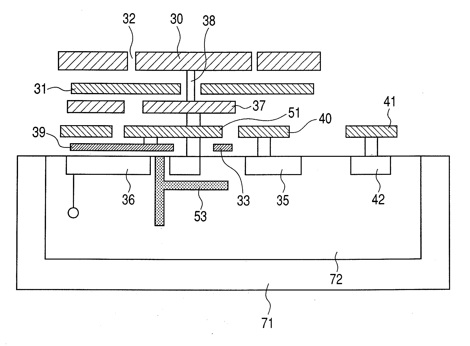
[0059]The Embodiment 2 of the present invention will be described based on FIG. 5. FIG. 5 is a plan view of a pixel layout for illustrating the pixel configuration of a reflection type liquid crystal display apparatus according to Embodiment 2. In Embodiment 2, the diffusion region 36 of the Embodiment 1 is arranged in an U shape. In Embodiment 2, an n-type diffusion region 36 that is a suction port of the photo carriers is arranged in an U shape so as to surround the periphery of a drain region 34. The n-type diffusion region 36 can be provided so as to surround except for a channel region where a gate electrode 33 connected to a gate wiring 62 and a region between a source region 35 and a drain region 33, are superposed. In addition, the n-type diffusion region 36 that is the suction port of the photo carriers is not limited to the U shape, for example, the n-type diffusion region 36 may be provided so as to surround the surroundings of the drain region 34 in an L shape viewed fro...
embodiment 3
[0060]Now, Embodiment 3 of the present invention will be described in detail based on FIGS. 6A and 6B.
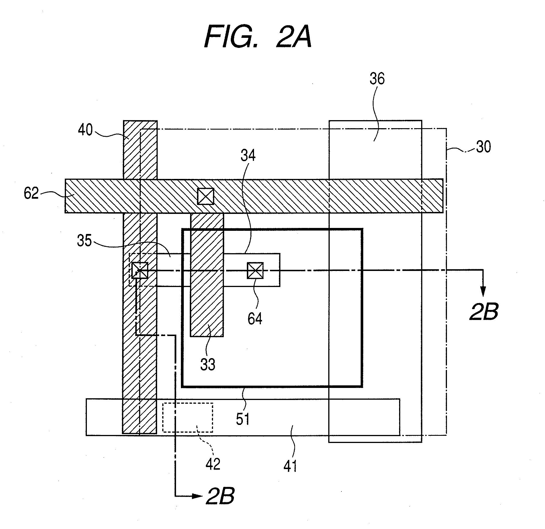
[0061]In FIGS. 6A and 6B, a pixel part used for a reflection type liquid crystal display apparatus according to Embodiment 3 of the present invention. FIG. 6A is a plan view of the pixel part, and FIG. 6B is a cross-sectional view of the pixel part. Here, similar components as those in Embodiment 1, are denoted by the same reference numerals as those in Embodiment 1, and detailed description thereof will be eliminated.
[0062]In Embodiment 3, in addition to the components in Embodiment 1, a p-type region 50 is formed between a drain region 34 and a diffusion region 36. The p-type region 50 has a function of a potential barrier so that electrons, photo carriers produced inside a p type Si substrate 70, hardly reach to the drain region 34. As shown in FIG. 6B, the p type Si substrate 70 preferably locates from the surface to the deep inside of the p type Si substrate 70. However, the pr...
PUM
 Abstract
Description
Claims
Application Information
 - Generate Ideas
- Intellectual Property
- Life Sciences
- Materials
- Tech Scout
- Unparalleled Data Quality
- Higher Quality Content
- 60% Fewer Hallucinations
Browse by: Latest US Patents, China's latest patents, Technical Efficacy Thesaurus, Application Domain, Technology Topic, Popular Technical Reports.
© 2025 PatSnap. All rights reserved.Legal|Privacy policy|Modern Slavery Act Transparency Statement|Sitemap|About US| Contact US: help@patsnap.com