

Low-foaming gas processing compositions and uses thereof
a gas processing composition and low foam technology, applied in the field of low foam gas processing compositions, can solve the problems that the antifoaming technology is generally not well suited to the reduction of foam
- Summary
- Abstract
- Description
- Claims
- Application Information
AI Technical Summary
Benefits of technology
Problems solved by technology
Method used
Image

Examples
example 1
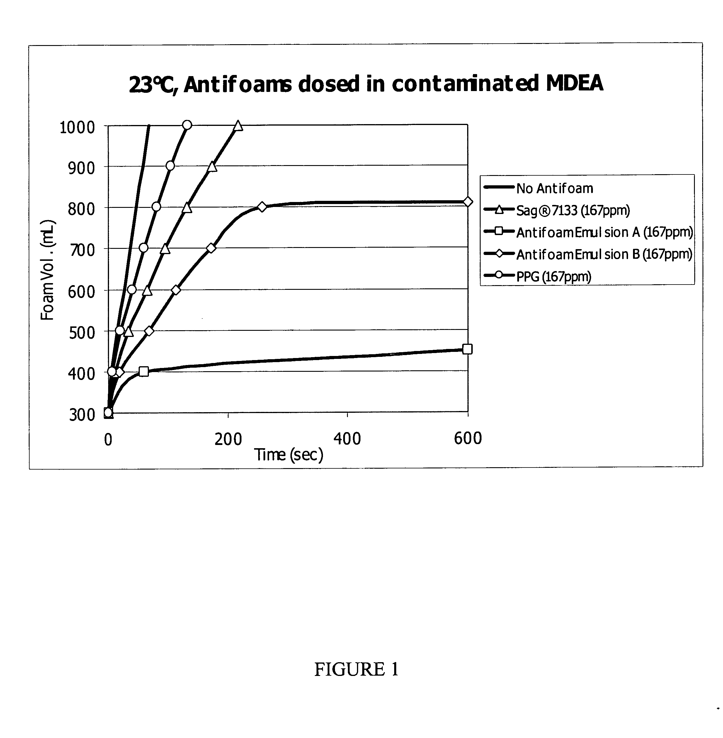
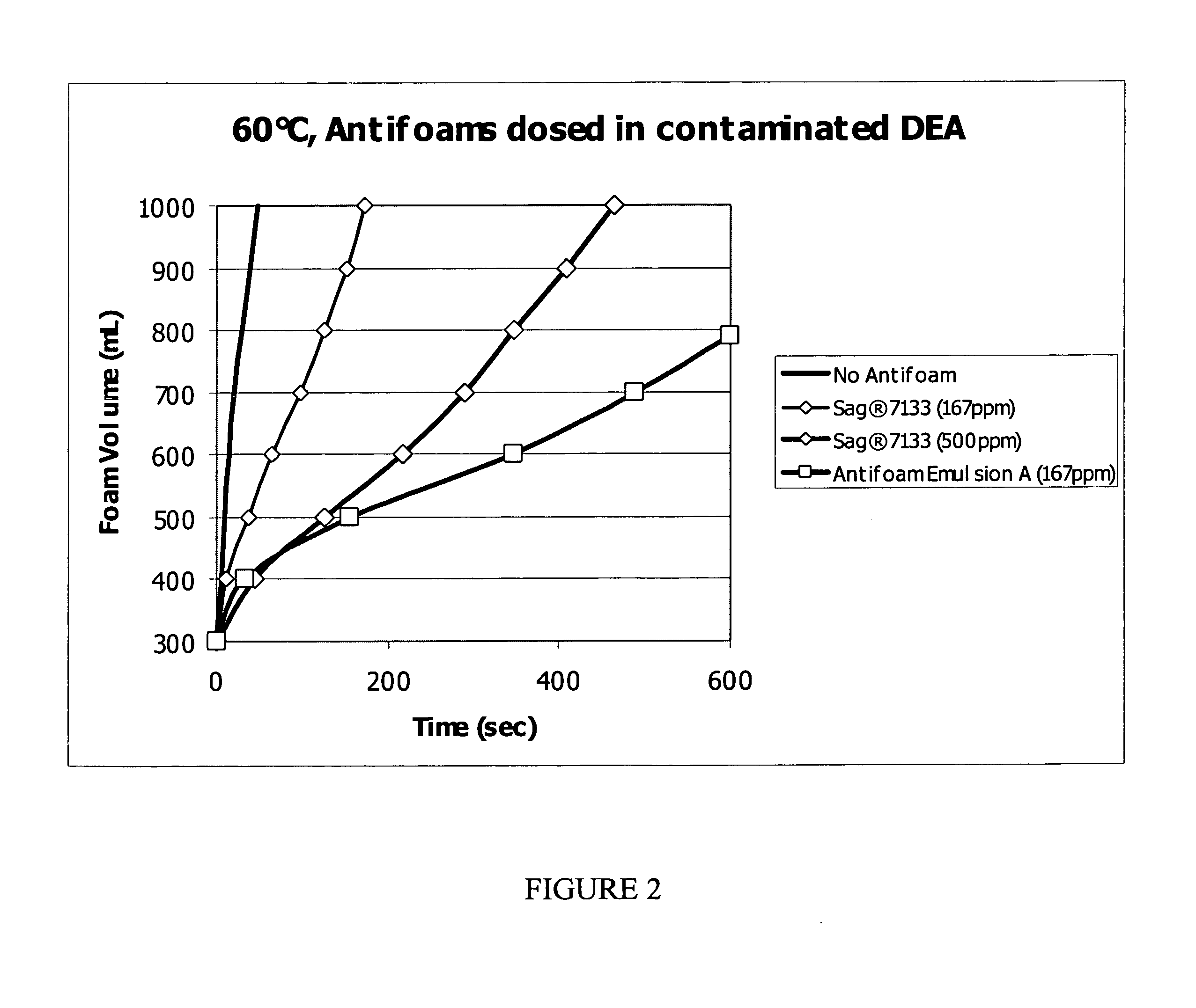
[0088] A gas processing composition was prepared by first making Antifoam Emulsion A. The emulsion contained 15% Sag 8200 silicone antifoam, 0.25% of a polydimethylsiloxane-polyalkylene copolymer which contained 40% polyethylene oxide, with a methyl end-group, and had a molecular weight of 10,000 Daltons, 1.5% of a polydimethylsiloxane-polyalkylene copolymer which contained 15% polyethylene oxide, 30% polypropylene oxide, with a methyl end-group and had a molecular weight of 50,000 Daltons and 0.25% of a polydimethylsiloxane-polyalkylene copolymer which contained 5% polyethylene oxide, 15% polypropylene oxide, with a methyl end-group and had a molecular weight of 20,000 Daltons, 30% polypropylene glycol with a molecular weight of 2000 Daltons, 1% Acusol 830, 0.23% Sodium hydroxide solution (20%), 0.1% Ucarcide 250 and 51.67% deionized water.
[0089] An amount of the above ANTIFOAM EMULSION A was then mixed with an aqueous amine solution (e.g., 30 to 40 weight percent of DEA or 40 to ...
example 2
[0090] The antifoaming composition was prepared by mixing one part of the above antifoaming precursor formulation, also referred to herein as Sag® 7133, with one part polypropylene glycol (PPG 2025), resulting in a composition referred to herein as ANTIFOAM EMULSION B.
[0091] To form the final gas processing composition, an amount of the above ANTIFOAM EMULSION B composition containing PPG was mixed with an aqueous amine solution (e.g., 30 to 40 weight percent of DEA or 40 to 50 weight percent MDEA in aqueous solution, which also contained 0.1 weight percent of an anionic surfactant, such as sodium lauryl sulfate to stabilize the foam) to provide a mixture having the antifoam composition in a minimum amount of approximately 1 ppm to a maximum of about 2000 ppm by weight of the silicone and polypropylenegylcol actives combination or by weight of the mixture.
example 3
Application Testing
[0092] In a 1000 mL clean volumetric cylinder, 300 mL of the test foaming solution, e.g., 30 to 40 wt % of DEA (diethanolamine) or 40 to 50 wt % MDEA (methyldiethanolamine) in water, which also contained zero point one weight percent of an anionic surfactant, such as sodium lauryl sulfate, to stabilize the foam, is placed into the volumetric cylinder. The volumetric cylinder is placed securely on the bench at ambient temperature or alternatively submersed and secured in a water bath preheated to the application temperature desired.
[0093] The antifoam is then accurately dosed into the solution under the meniscus layer by aid of a micropipette. A glass frit connected to a compressed gas source via a hollow glass rod and suitable hosing is then immersed and submerged into the testing solution. When the testing solution has reached the desired test temperature, compressed air is sparged into the testing solution at 4 L / min. The flow rate of the gas is controlled by...
PUM
| Property | Measurement | Unit |
|---|---|---|
| Fraction | aaaaa | aaaaa |
| Percent by mass | aaaaa | aaaaa |
| Percent by mass | aaaaa | aaaaa |
Abstract
Description
Claims
Application Information