Resectoscopic Device And Method

a technology of resectoscopic devices and methods, applied in the field of surgical devices, can solve the problems of increasing the risk of significant undesired tissue injury, reducing the ability to view what is happening with the instrument, and unplanned tissue injury,

Inactive Publication Date: 2007-10-18
LARSEN DANE M
View PDF11 Cites 183 Cited by
  • Summary
  • Abstract
  • Description
  • Claims
  • Application Information

AI Technical Summary

Benefits of technology

[0021] I have devised an instrument that can be used for resection of lesions or tissue that significantly reduces the above problems.
[0025] Various implementations of my invention can provide one or more of the following advantages: fully integrated functionality, reduction in trauma from insertion, reduction in time to perform a resection procedure, accurate targeting of tissue to be resected, automatic limiting of cutting depth, and / or capture and export of all resected tissue and debris. Moreover, certain implementations can be disposable, in whole or part, resulting in cost savings due to avoidance of cleaning and re-sterilization issues.
[0027] Variants implementing the invention provide a further pathological benefit not available with current resection tools like macerators, morcellators and electrosurgical loops or knives. One problem with macerators and micro-morcellators is that they destroy large amounts of tissue, rendering them less suitable for pathological examination. Electrosurgical loops or knives that cauterize as they cut create a zone of tissue destruction on the edges of each side of the cut that is typically about 10 microns deep. While this zone is considered pathologically acceptable, it nevertheless represents a zone of pathological uncertainty. Advantageously, with variants that implement the invention, the size of the resected tissue pieces can be larger than with currently available devices resulting in a greater ratio of undamaged to destroyed tissue and, consequently, a larger volume of pathologically examinable tissue.
[0028] Moreover, the protected nature of the cutting part of the device reduces or eliminates the risk of organ perforation, allowing for performing bi-directional resection—in contrast to the way surgeons are taught to perform resections with conventional instruments.
[0029] In addition, different variants can provide one or more of the following further advantages: quick functional change among operational modes (i.e. inflation, viewing, resection, irrigation, etc.); true dual conformation with immediate re-conformation; single hand manipulation and control; fluid switching and internalization with vacuum actuated flow boosting for accelerated tissue export; automatic transfer and capture of resected tissue; intrinsic depth of cut control; elimination of separate and discrete insertion or extraction of obturators, tissue choppers; elimination or reduction in the use of accessory instruments or undertaking cycles of insertion, cavity infusion, target acquisition, withdrawal, disassembly, reassembly, reinsertion, subsequent cavity reinfusion & target reacquisition, etc. saving effort, time and, consequently, money; unobstructed panoramic diagnostic viewing pre and post-resection; a protected resection mechanism; minimally traumatic instrument insertion and manipulation; and inhibition or prevention of organ perforation by an activated electrode under proper use.

Problems solved by technology

When an instrument is introduced into a body cavity during an operative procedure, in some cases, undesired tissue injury can be expected.
However, the risk of significant undesired tissue injury increases as the ability to view what is happening with the instrument decreases.
In other words, there is significantly greater risk of injury when an instrument must be inserted and used “blindly” (i.e. only by feel) than there is when the insertion path and area of use can be fully viewed.
While, in some cases, a potential undesirable injury such as a laceration or perforation may not present a significant risk so as to require remedial action (i.e. it will heal on its own), in other cases, such as an injury occurring in an organ like the uterus, intestine or bowel, a laceration or perforation can be life threatening—in the former organ due to excessive bleeding and, in the latter organs, by potentially causing peritonitis.
However, despite these advances organ lacerations and perforations still occur.
In addition, current resectoscopic instruments are generally complicated, balky, and often require multi-component reconfiguration during use.
Unfortunately, in certain organs, efficient removal of pathological tissue from an operative site remains problematic.
However, the process is rarely that straightforward.
More typically, the resection process is repeatedly interrupted by clogging of the tip assembly by tissue, or by sticking of the tissue to the loop itself.
In either case, diagnostically important pieces of tissue may be lost in the effluvium of uterine deflation, or dropped and lost in the handoff from surgeon to technician.
These geometric changes increase the size of the instrument and thus limit the use of the instrument to areas of the body or body cavity that can accommodate the size change and / or overall increased size.
In addition, none of these variant techniques meaningfully reduce organ perforation risk.
As a result, surgeons are forced to weigh and ultimately succumb to the trade-off between over-removal with its attendant risk of organ perforation or under-removal with the prospect that a repeat procedure may, at some point, be necessary.
Removal of pathological tissue from other organs routinely involves, to varying degrees, multiple steps of a somewhat analogous nature (i.e. multiple insertions / removals and issues relating to capture of resected pathological tissue) and thus analogous or similar problems exist with those operations as well.
As will be appreciated, the above example procedure to remove pathological tissue from the uterus is time consuming and typically takes between 30 and 60 minutes to perform.
With operating room costs exceeding several thousand dollars an hour, this can lead to substantial costs for a patient as well as the hospital in which the resection is performed.

Method used


Image

  • Resectoscopic Device And Method
  • Resectoscopic Device And Method
  • Resectoscopic Device And Method

Examples


Embodiment Construction

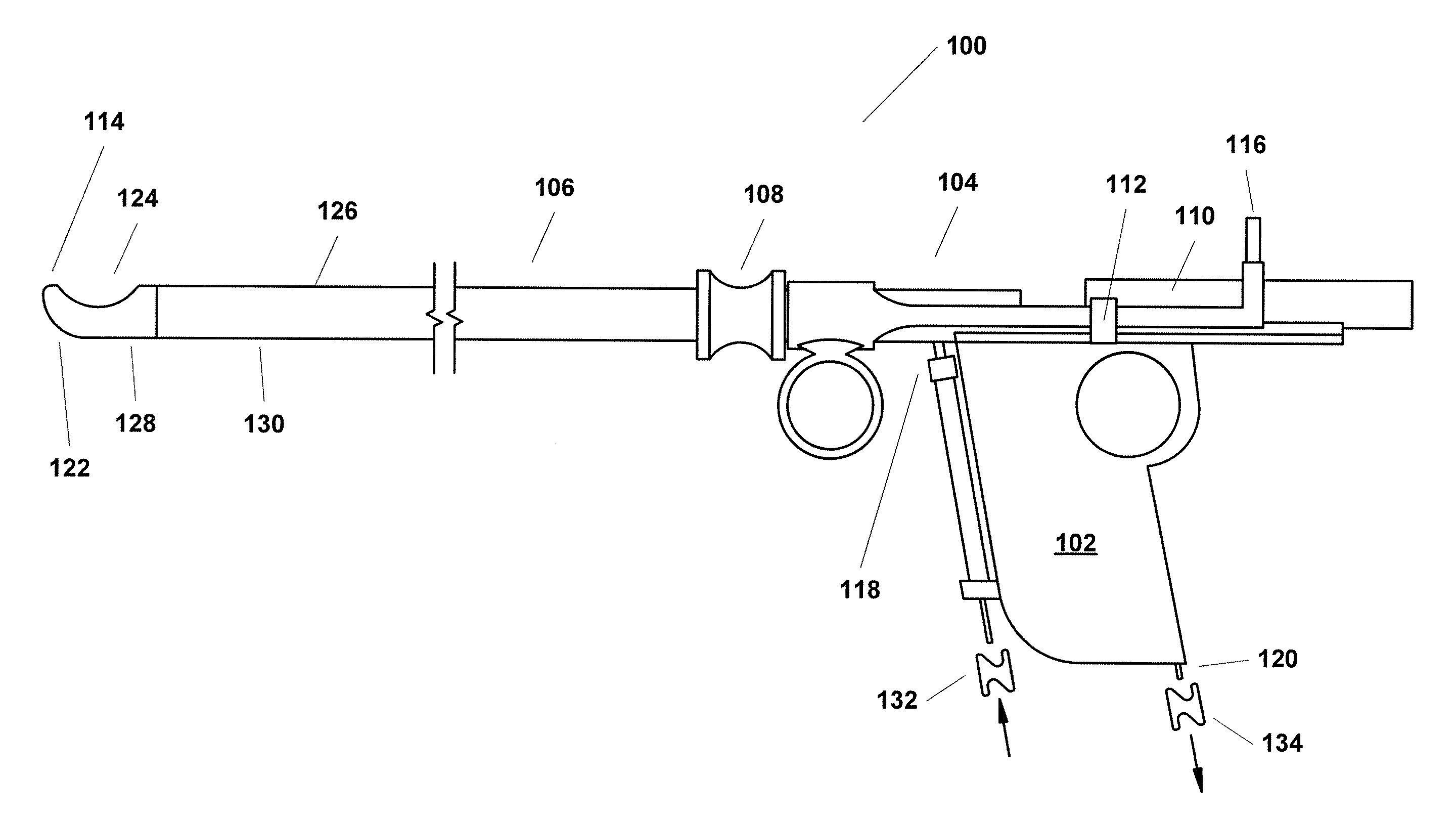
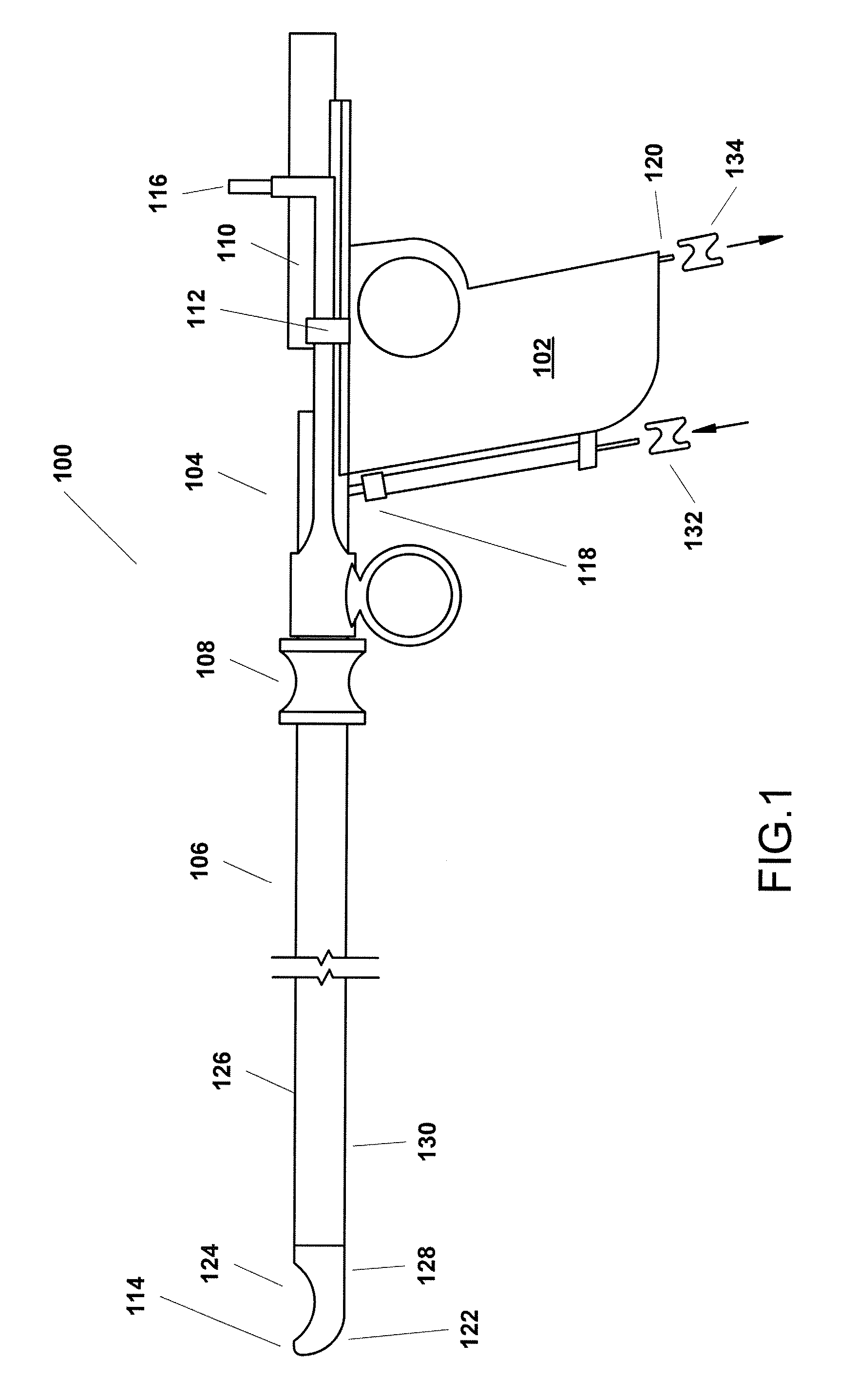
[0048]FIG. 1 is a simplified side view of one example variant of a resectoscope 100 incorporating the present invention. As shown in FIG. 1, this example resectoscope 100 is, in summary overview, made up of a partially hollowed out handle 102 and a control mechanism 104, both of which will be described in greater detail below, a shaft 106 connected at its proximal end to the handle 102, a port through which a telescope or other viewing apparatus, which may or may not involve use of fiber optic technology can be inserted (not shown), and a finger grip 108 on the shaft 106. The resectoscope 100 further includes a trolley mechanism 110 that facilitates movement of the telescope or other viewing apparatus that is contained within the shaft, a stop 112 that acts as a handle to allow manipulation of the trolley 110 and also limits movement of the trolley 110 mechanism towards the distal end 114 of the shaft, a power connector 116, a fluid inlet 118 and a vacuum port / fluid outlet 120. As c...


PUM


Abstract

A surgical instrument has a channel dimensioned to receive a viewing instrument and enable the viewing instrument to be moved to or from a position near an optically transparent portion of a blunt, enclosed distal end of a shaft to provide unobstructed viewing through the distal end, and a position to the proximal side of an enclosed working area to provide viewing of the enclosed working area. A surgical instrument also or alternatively has a fluid routing switch within a shaft which can selectively connect a fluid infusion channel to at least one fluid export pore or a return channel. A method involves moving a viewing instrument to or from a position near an optically transparent portion of a blunt, enclosed distal shaft end and a proximal side of an enclosed working area. A method also or alternatively involves changing a position of a fluid routing switch within the shaft.

Description

FIELD OF THE INVENTION [0001] The present invention relates to surgical devices and, more particularly, to surgical devices used for resection of tissue from within a body cavity. BACKGROUND TO THE INVENTION [0002] In surgical operations it is often necessary to insert tubular instruments into small body cavities in order to manipulate, modify or resect pathological tissues which may include, for example, lesions, polyps, cysts, fibroids, lymph nodes, choroid tissues, and other abnormal tissue growths, to name a few. When an instrument is introduced into a body cavity during an operative procedure, in some cases, undesired tissue injury can be expected. However, the risk of significant undesired tissue injury increases as the ability to view what is happening with the instrument decreases. In other words, there is significantly greater risk of injury when an instrument must be inserted and used “blindly” (i.e. only by feel) than there is when the insertion path and area of use can b...

Claims


Application Information

Patent Timeline
Patent Type & Authority Applications(United States)
IPC IPC(8): A61B1/00A61B1/12
CPCA61B1/12A61B1/126A61B18/18A61B1/307A61B17/32
Inventor LARSEN, DANE M.
Owner LARSEN DANE M
Why Eureka
Try Eureka