Prosthetic Devie for Cartilage Repair

a cartilage repair and prosthetic technology, applied in the field of prosthetic devices, can solve the problems of stress and friction, joint failure to permit motion, and limited regeneration capacity of articular cartilage, and achieve the effects of rapid cartilage growth, excellent mechanical stability, and improved stability of a prosthetic articular cartilage devi

Inactive Publication Date: 2007-10-18
STIFUNG DR H C ROBERT MATHYS
View PDF9 Cites 84 Cited by
  • Summary
  • Abstract
  • Description
  • Claims
  • Application Information

AI Technical Summary

Benefits of technology

[0017] It has been surprisingly found that the stability of a prosthetic articular cartilage device can be essentially improved by providing a stabilization area between said at least one layer of fibers and said base component and by a specific alignment of said fibers e.g. to more than 50% in parallel to the insertion axis of the base component, usually in a direction perpendicular to a top surface of the base component facing the fibers. The stabilization area allows to hold together the base component and the fibers by acting as a “adhesive component”. The specific alignment of the fibers in the layer perfectly mimics the cartilage and cartilage-like tissues providing an excellent mechanical stability. At the same time a basis for the ingrowth of articular chondrocytes is provided resulting in a rapid cartilage growth, thus assuring a long term cartilage replacement.

Problems solved by technology

Without articular cartilage, stress and friction would occur to the extent that the joint would not permit motion.
Articular cartilage has only a very limited capacity of regeneration.
If this tissue is damaged or lost by traumatic events, or by chronic and progressive degeneration, it usually leads to painful arthrosis and decreased range of joint motion.
The use of allograft material has been successful to some extent for small transplants, however, good quality allografts are hardly available.
Commonly, the replacement of cartilage tissue with solid permanent artificial inserts has been unsatisfactorily because the opposing articular joint surface is damaged by unevenness or by the hardness of the inserts.
It has been shown, however, that the function of the above construction has not been always satisfactory.
The reason is that said known prosthetic articular cartilage device is frequently unstable due to its structure and thus had to be replaced in the joint area by another surgical operation in to again repair cartilage joints such as knee and hip.

Method used


Image

  • Prosthetic Devie for Cartilage Repair
  • Prosthetic Devie for Cartilage Repair

Examples


example 1

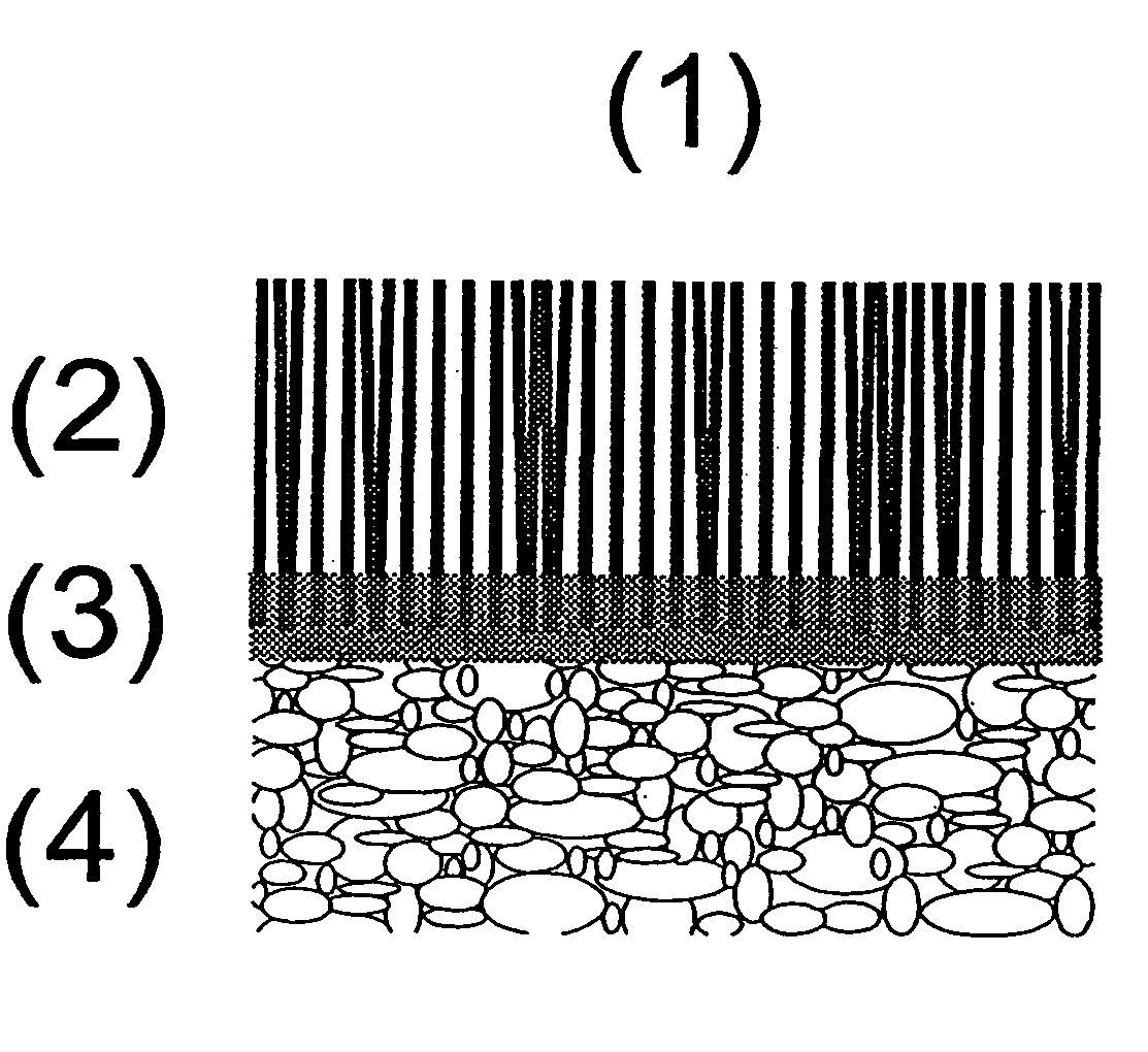
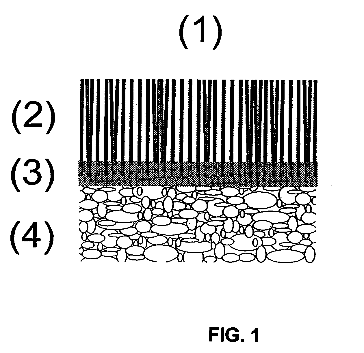
[0055] A prosthetic device is engineered from a porous interconnected cylindrical beta-tri-calcium-phosphate body sizing 5 mm in diameter and 10 mm in height, as subchondral anchor, and a 4 mm layer of oriented poly-hydroxy-ethyl-methacrylate (pHEMA) fibers with a diameter of 25 micrometer, as oriented fiber layer grafted to the anchor by a cement reaction. The vertical arrangement of the pHEMA fibers is random, but closely packed. The resulting prosthetic device is an ideal implant for cartilage repair.

[0056] A properly sized tubular chisel is introduced perpendicular to the defect site in the joint. In a first step in the implantation, the chisel is tapped into cartilage and the osseous base of the defect site. The defect size is exacted regarding depth and diameter to the specific dimensions of the prosthetic device. Subsequently, the anchor of the graft is soaked in a saline solution before the prosthetic device is inserted through the universal guide tool. No additional fixati...

example 2

[0057] A prosthetic device is engineered from a porous interconnected cylindrical hydroxyapatite body sizing 8 mm in diameter and 15 mm in height, as subchondral anchor, and a 4 mm layer of oriented and chemically derivatized methylcellulose fibers with diameters ranging between 1 and 50 micrometers, as oriented fiber layer. The fiber layer is obtained by embroidery and chemically grafted to the anchor by embedding. The vertical arrangement of the methylcelluose is a well-defined 2-D pattern. The resulting prosthetic device is an ideal implant for cartilage repair.

[0058] A properly sized tubular chisel is introduced perpendicular to the defect site in the joint. In a first step in the implantation, the chisel is tapped into cartilage and the osseous base of the defect site. The defect size is exacted regarding depth and diameter to the specific dimensions of the prosthetic device. Subsequently, harvested bone marrow stromal cells are added to the ceramic anchor. Next, the prostheti...

example 3

[0059] A prosthetic device is engineered from a porous interconnected cylindrical beta-tri-calcium-phosphate and calcium sulfate composite body sizing 12 mm in diameter and 10 mm in height, as subchondral anchor, and a 5 mm mixed layer of highly oriented polypropylene and polyetheretherketone fibers with a diameters ranging 0.5 to 30 micrometer, as oriented fiber layer. The vertical arrangement of the fibers is random, but closely packed. The resulting prosthetic device is an ideal implant for cartilage repair.

[0060] A properly sized tubular chisel is introduced perpendicular to the defect site in the joint. In a first step in the implantation, the chisel is tapped into cartilage and the osseous base of the defect site. The defect size is exacted regarding depth and diameter to the specific dimensions of the prosthetic device. Bone marrow stromal cells and platelet rich plasma is added to the anchor, and the prosthetic device is inserted subsequently by the universal guide tool. No...


PUM

PropertyMeasurementUnit
diameteraaaaaaaaaa
heightaaaaaaaaaa
heightaaaaaaaaaa

Abstract

A prosthetic device for repairing or replacing cartilage or cartilage-like tissue is described. The prosthetic device comprises at least one layer of highly oriented fibers, a base component and a stabilization area provided in between. Said fibers are aligned to more than 50% in a direction perpendicular to the base component.

Description

CROSS-REFERENCES TO RELATED APPLICATIONS [0001] The present application is claiming priority of European Patent Application No. 03 014 191.5, filed on Jun. 24, 2003 and PCT International Application No. PCT / EP2004 / 006530, filed on Jun. 17, 2004 the content of which is herein incorporated by reference.BACKGROUND OF THE INVENTION [0002] 1. Field of the Invention [0003] The present invention is directed to a prosthetic device for repairing or replacing cartilage or cartilage-like tissues. Said prosthetic devices are useful as articular cartilage substitution material and as scaffold for regeneration of articular cartilagenous tissues. [0004] 2. Description of the Related Art [0005] Articular cartilage tissue covers the ends of all bones that form diarthrodial joints. The resilient tissues provide the important characteristic of friction, lubrication, and wear in a joint. Furthermore, it acts as a shock absorber, distributing the load to the bones below. Without articular cartilage, str...

Claims


Application Information

Patent Timeline
Patent Type & Authority Applications(United States)
IPC IPC(8): A61B17/58A61F2/00A61F2/02A61F2/28A61F2/30A61F2/32A61F2/38A61L27/38A61L27/46A61L27/56
CPCA61F2/28A61L27/56A61F2/30965A61F2/32A61F2/38A61F2/3804A61F2002/30004A61F2002/30062A61F2002/30205A61F2002/30224A61F2002/30677A61F2002/30971A61F2210/0004A61F2230/0067A61F2230/0069A61F2250/0014A61F2310/00293A61L27/3654A61L27/3808A61L27/3813A61L27/3834A61L27/3852A61L27/46A61F2/30756
Inventor LUGINBUEHL, RETO
Owner STIFUNG DR H C ROBERT MATHYS
Why Eureka
Try Eureka