
Continous Butt Welding Method Using Plasma and Laser, and Method for Fabricating Metal Tube Using the Same

a butt welding and laser welding technology, applied in plasma welding apparatus, other domestic articles, manufacturing tools, etc., can solve the problems of difficult trace a delicate weld line, serious increase of welding cost, and generate pores in the welding portion, etc., to improve welding speed, small butt space, and small thickness

Inactive Publication Date: 2007-10-25
LG CABLE LTD (KR) +1
View PDF6 Cites 19 Cited by
  • Summary
  • Abstract
  • Description
  • Claims
  • Application Information

AI Technical Summary

Benefits of technology

[0009] The present invention is designed to solve the problems of the prior art, and therefore it is an object of the present invention to provide a welding method capable of improving a welding speed and also allowing elaborate welding for an object to be welded having a very small butt space and small thickness.

Problems solved by technology

However, the laser welding has disadvantages that its narrow focal radius makes it difficult to trace a delicate weld line as in the butt welding, and generates pores in the welding portion since it causes the key hole to be unstable.
In addition, in the case of the laser welding high-power laser should be used to accelerate a welding flux for improvement of productivity, resulting in serious increase of welding cost.
However, the arc welding has a disadvantage that it is unsuitable to weld an elaborate product with a narrow butt space (for example, 0.2 mm or less) because it has a large area of the heat source in the welding portion.
However, using two kinds of heat sources at the same time is not always advantageous.
For example the results obtained when two welding methods are used together may be inferior to a simple sum of results obtained by each of the heat sources, depending on a treatment order, a distance, an angle, a power and a welding speed of two heat sources.
Accordingly, laser welding using CO2 laser is currently used as such a welding method, but it is difficult to improve the productivity of metal tube only by the laser welding, as describe above.

Method used


Image

  • Continous Butt Welding Method Using Plasma and Laser, and Method for Fabricating Metal Tube Using the Same
  • Continous Butt Welding Method Using Plasma and Laser, and Method for Fabricating Metal Tube Using the Same
  • Continous Butt Welding Method Using Plasma and Laser, and Method for Fabricating Metal Tube Using the Same

Examples


Embodiment Construction

[0027] Hereinafter, preferred embodiments of the present invention will be described in detail referring to the accompanying drawings. Prior to the description, it should be understood that the terms used in the specification and appended claims should not be construed as limited to general and dictionary meanings, but interpreted based on the meanings and concepts corresponding to technical aspects of the present invention on the basis of the principle that the inventor is allowed to define terms appropriately for the best explanation. Therefore, the description proposed herein is just a preferable example for the purpose of illustrations only, not intended to limit the scope of the invention, so it should be understood that other equivalents and modifications could be made thereto without departing from the spirit and scope of the invention.

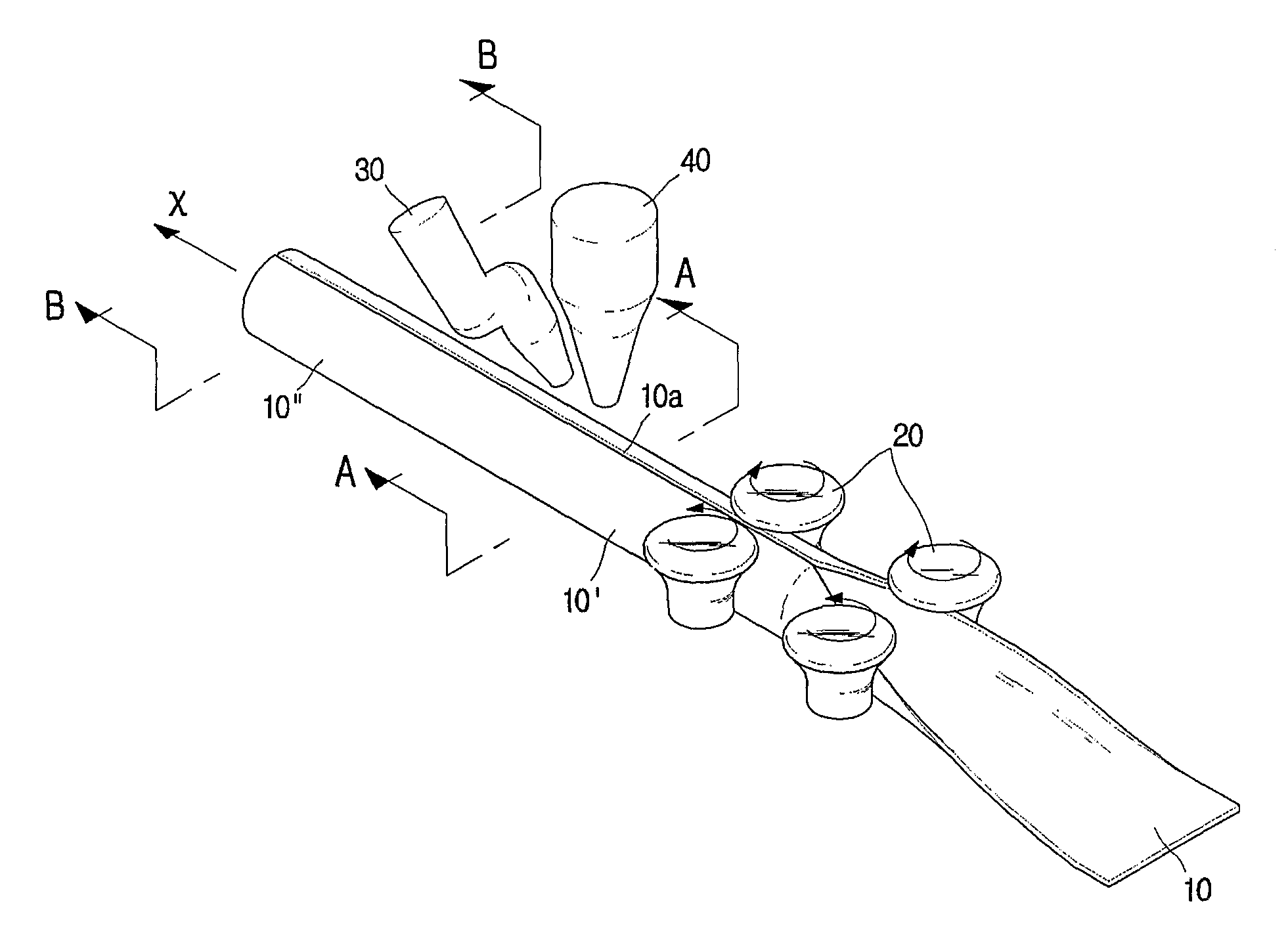
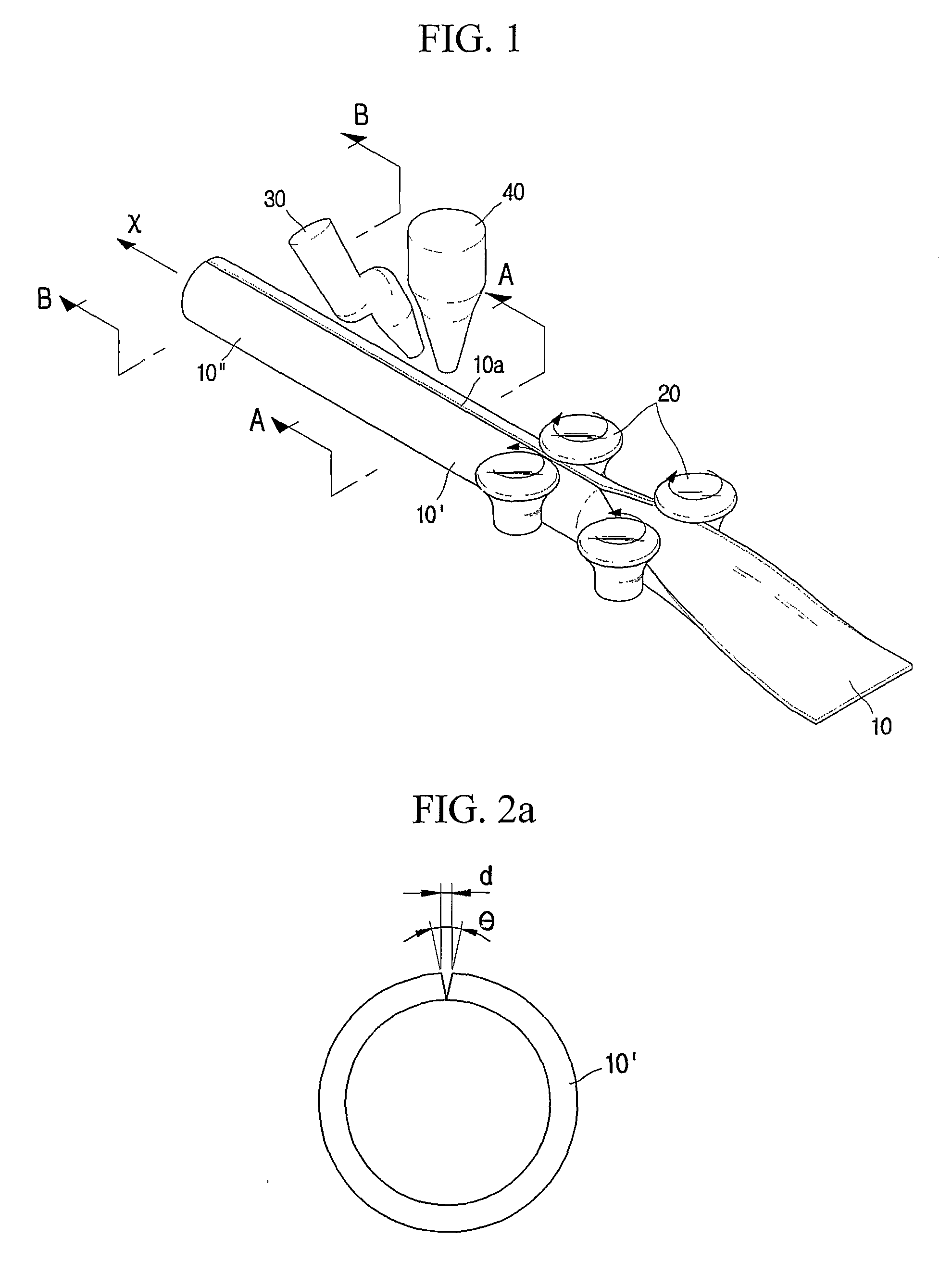
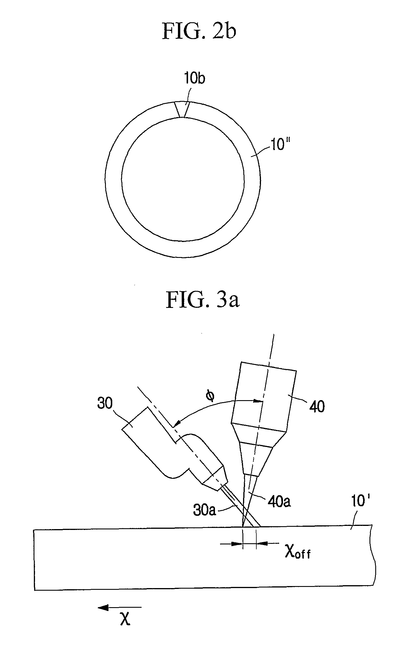
[0028]FIG. 1 is a schematic perspective view showing a device for fabricating a metal tube using a welding method and a method for fabricatin...


PUM

PropertyMeasurementUnit
distanceaaaaaaaaaa
angleaaaaaaaaaa
angleaaaaaaaaaa

Abstract

A continuous butt welding method using plasma and laser, and a method for fabricating a metal tube using the butt welding method are disclosed. The butt welding method conducts a laser welding and a plasma welding together against an object to be welded, which has a very narrow butt space. In particular, the plasma is prior to the laser so that the object is preheated by the plasma, and then a preform is melted by a laser beam in order to accomplish the major welding. In addition, a metal sheet is bent to have a circular section so that its both ends are faced with each other, and then the faced both ends are welded using the aforementioned butt welding method, thereby fabricating a metal tube. The butt welding method and the metal tube fabricating method mentioned above remarkably improve a welding speed and productivity of metal tube.

Description

TECHNICAL FIELD [0001] The present invention relates to a butt welding method of metal materials and a method for fabricating a metal tube using the same, and more particularly to a welding method for improving a welding speed by using two kinds of heat sources together, and a method for fabricating a metal tube using the welding method. BACKGROUND ART [0002] Laser welding and arc welding have been widely used to face and weld two metals with each other. [0003] The laser welding has advantages that it is possible to precisely weld a fine part due to its small heat-affected zone because it may focus a heat source (for example, a laser beam) on a very small size, and to conduct seam welding (or, deep penetration welding) by forming a key hole. However, the laser welding has disadvantages that its narrow focal radius makes it difficult to trace a delicate weld line as in the butt welding, and generates pores in the welding portion since it causes the key hole to be unstable. In additio...

Claims


Application Information

Patent Timeline
Patent Type & Authority Applications(United States)
IPC IPC(8): B23K26/00B23K31/02B23K10/02B23K26/14B23K26/26B23K26/32B23K26/42B23K33/00
CPCB23K10/02B23K26/265B23K26/3206B23K26/421B23K33/006B23K26/1429B23K2203/04B23K2203/10B23K2203/12B23K2203/14B23K2201/06B23K26/32B23K26/262B23K26/348B23K26/60B23K2101/06B23K2103/04B23K2103/05B23K2103/10B23K2103/12B23K2103/14B23K2103/50B23K31/02
Inventor LEE, SANG-HOONWON, YONG-HEEKIM, TAE-SEONGLEE, TAE-JUNGBYUN, JUNG-HOONNA, SUCK-JOOYOON, SUK-HWANHWANG, JAE-RYUN
Owner LG CABLE LTD (KR)
Learn More