Varactor

a technology of varactor and spherical structure, which is applied in the direction of spherical structure, basic electric elements, electrical apparatus, etc., to achieve the effect of improving the quality factor and increasing the unit capacitan

Active Publication Date: 2007-10-25
UNITED MICROELECTRONICS CORP
View PDF8 Cites 22 Cited by
  • Summary
  • Abstract
  • Description
  • Claims
  • Application Information

AI Technical Summary

Benefits of technology

[0006] The objective of the present invention is to provide a varactor, which can increase the unit capacitance and improve the quality factor of the varactor.

Problems solved by technology

Accordingly, how to increase the ratio of the area of the upper electrode to the sum of the area of the bottom electrode to improve the unit capacitance becomes an important issue of current development of the varactor.

Method used


Image

  • Varactor
  • Varactor
  • Varactor

Examples


Embodiment Construction

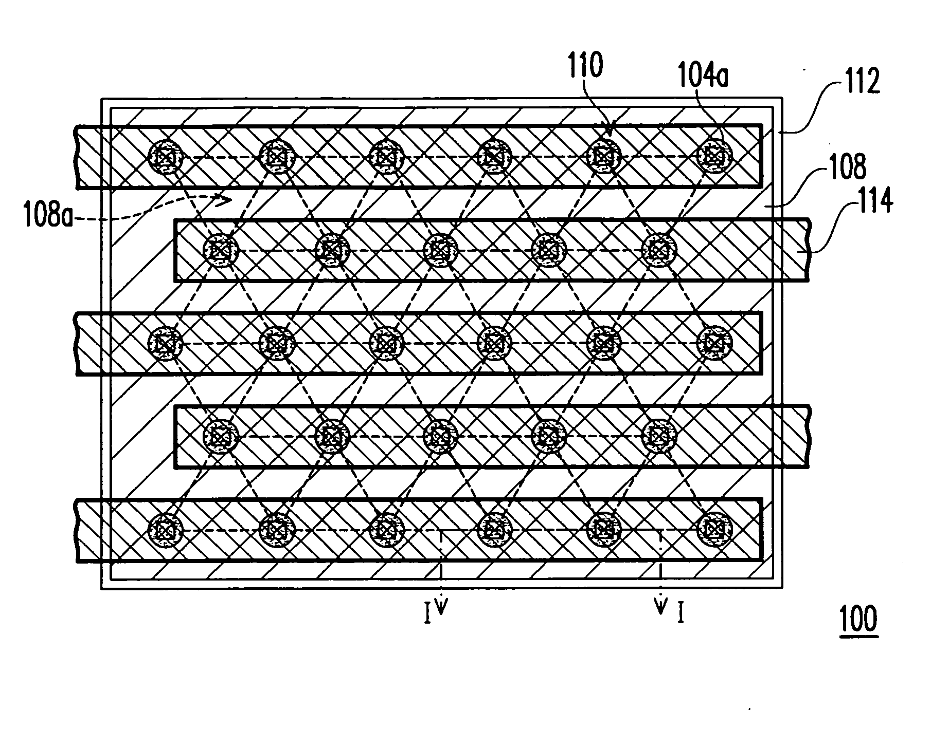
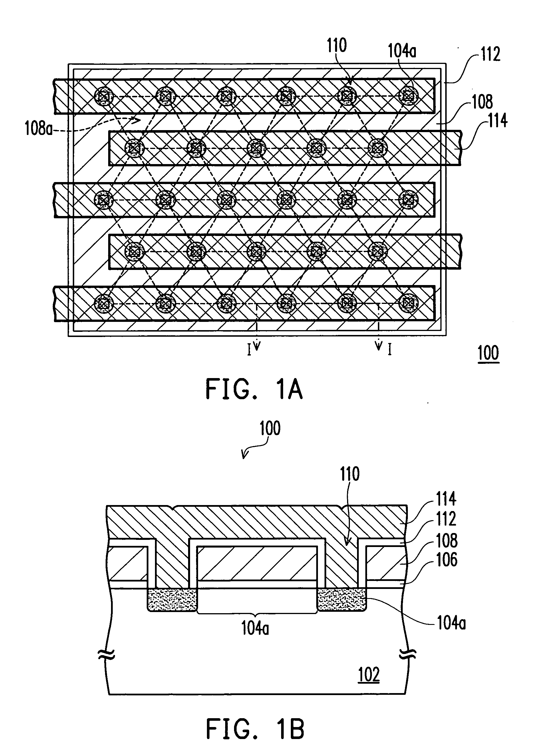
[0035]FIG. 1A is a top view of a varactor according to a preferred embodiment of the invention. FIG. 1B is a cross-sectional view of a varactor along a line I-I in FIG. 1A. As shown in FIG. 1A together with FIG. 1B, a varactor 100 is located on a substrate 102, wherein the varactor 100 comprises a bottom electrode 104. The bottom electrode 104 has several doped regions 104a in the substrate 102. The substrate 102 can be, for example but not limited to, a semiconductor substrate formed from silicon, germanium, silicon germanium, arsenic gallium or arsenic indium. Furthermore, the substrate 102 can be, for example but not limited to, a multi-layered substrate such as a silicon-on-insulator substrate or silicon / silicon germanium. The dopants in the doped region 104a can be, for example but not limited to, P conductive type ions or N conductive type ions. Additionally, the doped region 104a in the substrate 102 can be, for example, arranged in an array with several columns and several r...


PUM


Abstract

A varactor on a substrate is provided. The varactor comprises a bottom electrode, an upper electrode, a first dielectric layer and a conductive layer. The bottom electrode has several doped regions arranged in the substrate as an array with several rows and several columns, wherein the doped regions in adjacent columns are arranged alternatively. The upper electrode is located over the substrate and the upper electrode is composed of several electrode locations and has several openings, wherein each opening exposes the corresponding doped region. Furthermore, each electrode location is surrounded by three doped regions. The first dielectric layer is located between the substrate and the upper electrode. The conductive layer is located over the upper electrode, wherein the conductive layer and the upper electrode are isolated from each other and the conductive layer and the doped regions are electrically connected to each other.

Description

BACKGROUND OF THE INVENTION [0001] 1. Field of Invention [0002] The present invention relates to a semiconductor structure. More particularly, the present invention relates to a varactor structure. [0003] 2. Description of Related Art [0004] In a typical communication system, information signals, such as television program, will be tuned and placed on high frequency carrier waves to facilitate transmission of signals. Lots of information signals are transmitted simultaneously due to the properties of different frequencies having different carrier wave signals. Therefore, a receiver in a communication system is required to use a voltage controlled oscillator (VCO) to separate information signals from the carrier waves. In a VCO, a LC (inductance-capacitance) circuit comprised of the varactor and the inductance is included. The oscillation frequency of the VCO is modified by the properties of the capacitance of the varactor being modified according to the tuning of the voltage. [0005]...

Claims


Application Information

Patent Timeline
Patent Type & Authority Applications(United States)
IPC IPC(8): H01L29/93
CPCH01L29/94H01L29/93
Inventor HUNG, CHENG-CHOUTSENG, HUA-CHOU
Owner UNITED MICROELECTRONICS CORP
Why Eureka
Try Eureka