Diagnosis system for vane-type variable valve timing controller

a technology of variable valve timing controller and diagnostic system, which is applied in the direction of valve arrangement, machines/engines, mechanical equipment, etc., can solve the problems of abnormal advance/retard operation, valve not operating normally, and deteriorating mounting properties

Inactive Publication Date: 2007-11-01
DENSO CORP
View PDF4 Cites 25 Cited by
  • Summary
  • Abstract
  • Description
  • Claims
  • Application Information

AI Technical Summary

Benefits of technology

[0010] An object of the present invention is to provide a diagnosis system of a vane-type variable valve timing controller which can quickly detect abnormality in an advance / retard operation thereof during engine operating.
[0012] When the entire system is operating normally, during retard operating, the drain switching valve in the side of the advance hydraulic chamber is opened, making the operating oil in the advance hydraulic chamber be easily drained through the drain switching valve and at the same time, the drain switching valve in the side of the retard hydraulic chamber is closed to make the function of the one-way valve in the side of the retard hydraulic chamber be effected well, preventing reverse flow of the operating oil from the retard hydraulic chamber with the one-way valve, while performing control of filling the operating oil in the retard hydraulic chamber. Hereby, even at a low hydraulic pressure, coping with the torque fluctuations in the advance direction transmitted from the cam shaft, the reverse flow of the operating oil from the retard hydraulic chamber is prevented with the one-way valve and at the same time, the hydraulic pressure is efficiently supplied to the retard hydraulic chamber, improving the retard responsiveness.
[0013] In addition, during advance operating, the drain switching valve in the side of the retard hydraulic chamber is opened, making the operating oil in the retard hydraulic chamber be easily drained through the drain switching valve and the drain switching valve in the side of the advance hydraulic chamber is closed to make the function of the one-way valve in the side of the advance hydraulic chamber be effected well, preventing reverse flow of the operating oil from the advance hydraulic chamber with the one-way valve, while performing control of filling the operating oil in the advance hydraulic chamber. Hereby, even at a low hydraulic pressure, coping with the torque fluctuations in the retard direction transmitted from the cam shaft, the reverse flow of the operating oil from the advance hydraulic chamber is prevented with the one-way valve and at the same time, the hydraulic pressure is efficiently supplied to the advance hydraulic chamber, improving the advance responsiveness.
[0014] In consideration of such characteristic, the present invention determines whether or not responsiveness in an advance / retard operation is within a normal range based upon a changing rate of a VTC displacement angle during advance / retard operating to determine presence / absence of abnormality in the corresponding advance / retard operation, thereby enabling abnormality in the advance / retard operation during engine operating to be quickly detected.
[0016] When both of the drain switching valves in the side of the advance hydraulic chamber and the side of the retard hydraulic chamber operate normally during hold operating, both of the drain switching valves close. Therefore, if both the one-way valves are normal, the reverse flow-preventing function of both the one-way valves can be effectively applied. However, when there occurs an open abnormality state where either one of the drain switching valves (or one-way valves) stops at a state of being opened, even during hold operating, either one of the drain switching valves (or one-way valves) is fixed at the state of being opened. Accordingly, when the holding current is vibrated in a certain amplitude during hold operating to determine a changing amount of the VTC displacement angle due to the vibration of the holding current, if both of the drain switching valves normally close and the function of the one-way valve is effectively applied, leak of the hydraulic pressure from both of the hydraulic chambers is effectively prevented with both of the one-way valves and therefore, a changing amount of the VTC displacement angle is reduced. When either one of the drain switching valves (or one-way valves) is at an open abnormality state, the hydraulic pressure in the hydraulic chamber at a side where the open abnormality occurs is leaked through the drain switching valve (or one-way valve) and reduced. In consequence, a balance in hydraulic pressure between both of the hydraulic chambers is off and it is hard to maintain the VTC displacement angle at a constant position, so that a changing amount of the VTC displacement angle increases. Accordingly, if the holding current is vibrated during hold operating as in the case of the present invention, the determination can be made as to presence / absence of abnormality in a drain switching valve and / or a one-way valve based upon whether or not the changing degree of the VTC displacement angle due to the vibration of the holding current is great. As a result, abnormality in the drain switching valve or the one-way valve can be quickly detected.
[0019] When both of the drain switching valves in the side of the advance hydraulic chamber and in the side of the retard hydraulic chamber operate normally during hold operating, both of the drain switching valves close. Therefore, if both of the one-way valves are normal, the reverse flow preventing function of both of the one-way valves can be effectively applied. However, when there occurs an open abnormality state where either one of the drain switching valves (one-way valves) stops at a state of being opened, even during hold operating either one of the drain switching valves (or one-way valves) is fixed at the state of being opened. Therefore, When either one of the drain switching valves (or one-way valves) is at an open abnormality state during hold operating, the hydraulic pressure in the hydraulic chamber at a side where the open abnormality occurs is leaked through the drain switching valve (or one-way valve) and reduced. In consequence, a balance in hydraulic pressure between both of the hydraulic chambers is off and it is hard to maintain the VTC displacement angle at a constant position, so that there occurs the phenomenon that a changing amount of the VTC displacement angle increases. Considering this characteristic, the present invention is designed, during hold operating, to determine whether or not open abnormality occurs in a drain switching valve and / or a one-way valve based upon the changing amount of the VTC displacement angle within a certain period. As a result, open abnormality in the drain switching valve or the one-way valve can be quickly detected.

Problems solved by technology

In this variable valve timing controller, however, an armature in the hydraulic control valve is driven by an electric variable force solenoid to increase the entire length of the controller in the cam shaft direction, deteriorating the mounting properties.
It is found out during the developing process of the variable valve timing mechanism that it has the possibility that when an engine operates for a long term in an endurance test or the like, foreign matter is forced to be entered into a drain switching valve or a one-way valve or these valve bodies are stuck, so that the drain switching valve or the one-way valve does not operate normally (possibility that an advance / retard operation becomes abnormal).
Since this abnormality deteriorates the engine performance, it is required to detect it as soon as possible to let a driver to be informed of it for repair.

Method used


Image

  • Diagnosis system for vane-type variable valve timing controller
  • Diagnosis system for vane-type variable valve timing controller
  • Diagnosis system for vane-type variable valve timing controller

Examples


embodiment 1

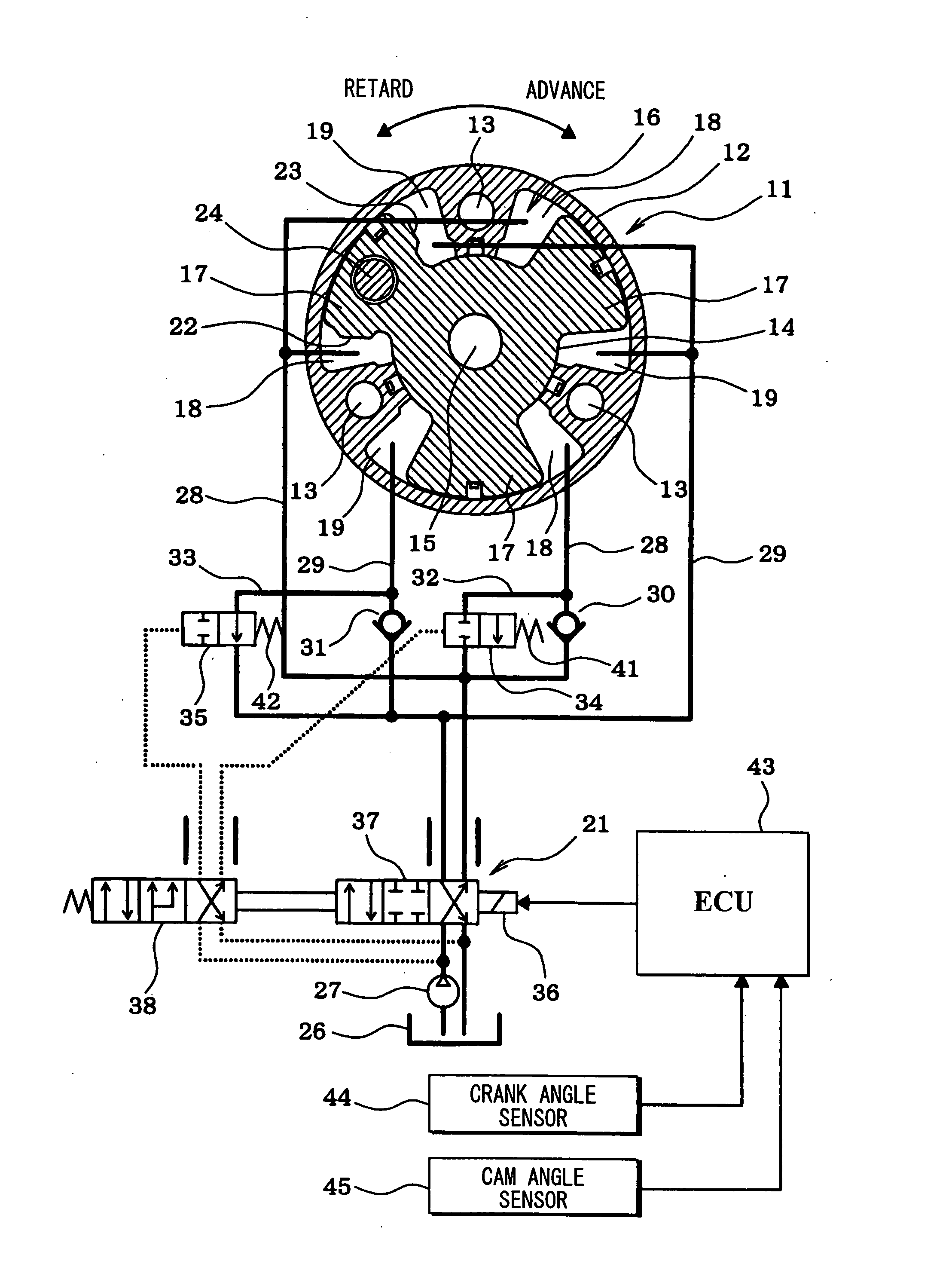
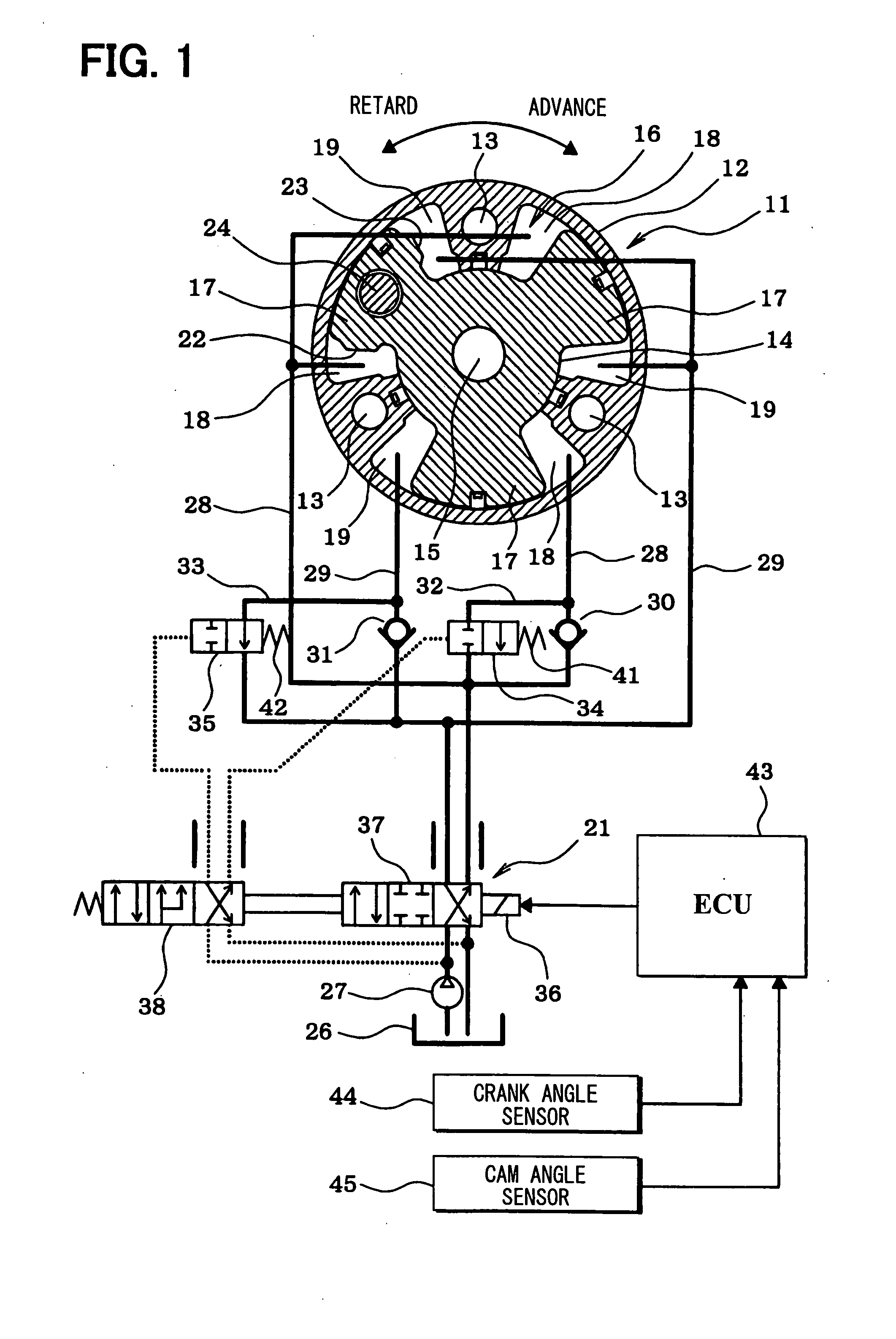
[0045] First, a structure of a vane-type variable valve timing controller 11 will be explained with reference to FIG. 1. A housing 12 of the variable valve timing controller 11 is clamped and fixed to a sprocket rotatably supported at an outer periphery of a cam shaft in an intake side or an exhaust side (not shown) by bolts 13. In consequence, rotation of a crankshaft for an engine is transmitted through a timing chain to the sprocket and the housing 12 and the sprocket and the housing 12 rotate in a timed relation to the crankshaft. A vane rotor 14 is accommodated inside the housing 12 so as to rotate relative thereto and is clamped and fixed to one end of the camshaft by a bolt 15.

[0046] A plurality of vane accommodating chambers 16 for accommodating a plurality of vanes 17 at an outer periphery of the vane rotor 14 so as to rotate in the advance direction or the retard direction relative to the housing 12 are defined inside the housing 12 and each vane accommodating chamber 16 ...

embodiment 2

[0113] Embodiment 2 detects abnormality by using the following method, considering that in a region of a high-rotation side where an engine rotational speed is more than a predetermined value, the drain switching valves 34 and 35 respectively are forcibly opened due to the rotational centrifugal force all the time regardless of the control hydraulic pressure in the drain switching valves 34 and 35 respectively, creating the state where the functions of the respective one-way valves 30 and 31 do not work.

[Abnormality Diagnosis in a Region at a Low Rotation Side]

[0114] During holding operating, in a region of a low rotation side less than a predetermined rotational speed where the drain switching valves 34 and 35 of both the sides are closed if they are normal, as shown in FIG. 8, the holding current (hold duty) of the hydraulic control valve 21 is vibrated (dither) in a predetermined amplitude / cycle to determine a changing degree of the VTC displacement angle by the vibration of th...

embodiment 3

[0178] In Embodiment 3, the open abnormality will be detected as follows.

[0179] When both of the drain switching valves 34 and 35 in the side of the advance hydraulic chamber 18 and in the side of the retard hydraulic chamber 19 operate normally during holding operating, both of the drain switching valves 34 and 35 close. Therefore, when both of the one-way valves 30 and 31 are normal, a reverse flow prevention function of each of the one-way valves 30 and 31 can be made to effectively operate. However, when there occurs the open abnormality state where either one of the drain switching valves 34 and 35 (or the one-way valves 30 and 31) remains to be opened, either one of the drain switching valves 34 and 35 (or the one-way valves 30 and 31) is fixed in a state of being opened even during the holding operating. Accordingly, when either one of the drain switching valves 34 and 35 (or the one-way valves 30 and 31) is in an open abnormality state, the hydraulic pressures in the hydrau...


PUM


Abstract

One-way valves are provided in a hydraulic pressure supply passage in an advance hydraulic chamber and a hydraulic pressure supply passage in a retard hydraulic chamber respectively. A drain oil passage bypassing each of the one-way valves is provided in the hydraulic pressure supply passage in the each hydraulic chamber to be in parallel therewith. A drain switching valve is provided in the each drain oil passage. A drain switching control function for switching the hydraulic pressure driving the each drain switching valve is integral with a function of the hydraulic control valve for controlling the hydraulic pressure supplied to the advance hydraulic chamber and the retard hydraulic chamber. It is determined whether the responsiveness of an advance / retard operation is in a normal range based upon a changing rate of the VTC displacement angle during advance / retard operating, thereby determining presence / absence of abnormality in the advance / retard operation.

Description

CROSS REFERENCE TO RELATED APPLICATION [0001] This application is based on Japanese Patent Applications No. 2006-119354 filed on Apr. 24, 2006, No. 2006-122763 filed on Apr. 27, 2006, and No. 2006-124825 filed on Apr. 28, 2006, the disclosures of which are incorporated herein by reference. FIELD OF THE INVENTION [0002] The present invention relates to a diagnosis system for a vane-type variable valve timing controller in which one-way valves are disposed in a hydraulic supply passage of an advance hydraulic chamber and in a hydraulic supply passage of a retard hydraulic chamber respectively for preventing reverse flow of operating oil from the respective hydraulic chambers. BACKGROUND OF THE INVENTION [0003] A basic arrangement of a vane-type variable valve timing controller is, as shown in U.S. Pat. No. 6,330,870B1, adapted in such a manner that a housing rotating in a timed relation to a crank shaft of an engine is disposed coaxially with a vane rotor connected to a cam shaft of a...

Claims


Application Information

Patent Timeline
Patent Type & Authority Applications(United States)
IPC IPC(8): F01L1/34
CPCF01L1/022F01L1/3442F01L2001/34426F01L2820/042F01L2001/34469F01L2800/00F01L2820/041F01L2001/34436
Inventor NOZAWA, MASAEIHAYAMI, TOSHIFUMINAGASHIMA, WATARU
Owner DENSO CORP
Why Eureka
Try Eureka