
Ultrasensitive magnetoelectric thin film magnetometer and method of fabrication

a thin film magnetometer, ultra-sensitive technology, applied in the direction of magnetostrictive property measurement, digital storage, instruments, etc., can solve the problems of high-sensitivity me devices, cumbersome and unwieldy apparatus setup, expensive instruments or tools, etc., to achieve the effect of superior operational characteristics

Active Publication Date: 2007-11-01
MARYLAND UNIV OF
View PDF2 Cites 37 Cited by
  • Summary
  • Abstract
  • Description
  • Claims
  • Application Information

AI Technical Summary

Benefits of technology

[0025] It is an object of the present system to provide an ultrasensitive magnetoelectric thin film magnetometer capable of superior operational characteristics at room temperatures based upon a cantilever concept.
[0028] It is a further object of the present system to provide a method for forming an ultrasensitive magnetoelectric thin film magnetometer using a thin film deposition technique in combination with various material removal steps to form a cantilever based magnetoelectric thin film magnetometer having superior operational characteristics.
[0032] Since the underlying cantilever beam is of a small thickness, the clamping effect of the active structure with the material of the cantilever beam is minimized or negligible (especially in the case of freestanding structures).

Problems solved by technology

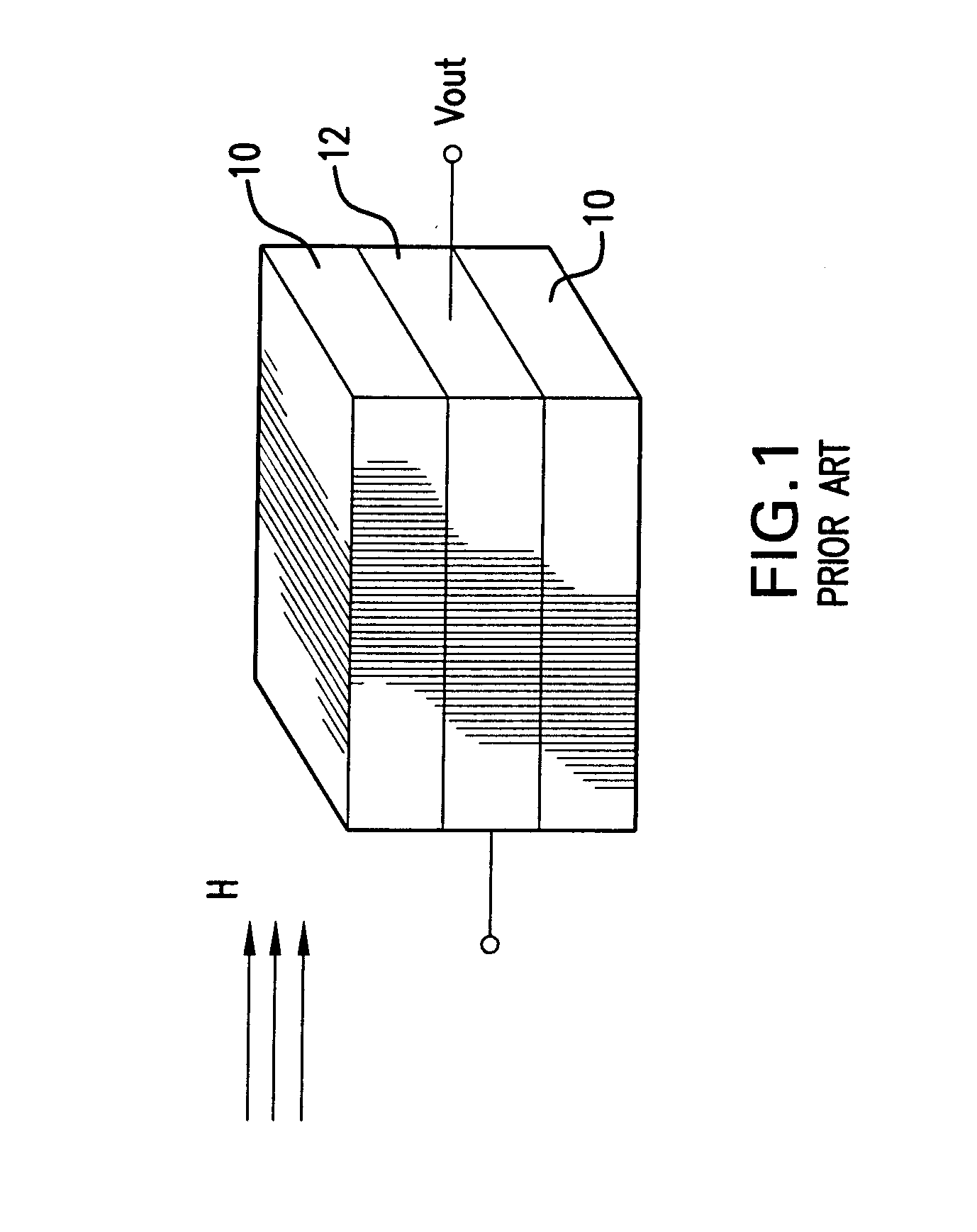
In the highest sensitivity limit, Superconducting Quantum Interference Devices (SQUIDs) have long served as the ultimate detectors with the sensitivity of ˜10−15 T / Hz1 / 2 operating at 4.2 K. Recently, a number of alternative techniques have been demonstrated including an atomic magnetometer with subfemtotesla resolution and magnetoresistive sensors with 32×10−15 T (32 FT) sensitivity at 77 K. These techniques have significant drawbacks in that they require cryogenics and / or a cumbersome and unwieldy apparatus setup.
From a practical and commercial point of view, these drawbacks inevitably translate to very expensive instruments or the tools not being suitable for everyday applications.
Disadvantageously, high sensitivity ME devices demonstrated to date have been fabricated using bulk or hybrid laminate materials and are typically mm˜cm in dimensions.
However, due to the fact that ME devices rely on their layers being able to display mechanical flexibility, one disadvantage of thin film structures is that they inevitably have to be deposited on substrates thus being exposed to the substrate clamping effect which deteriorates the performance characteristics of ME devices.
Despite the previous developments in the field of thin film magnetoelectric materials, such have been supported by substrates thus inevitably suffering, through the substrate clamping effect, a deterioration in their coupling characteristics.
Also, to date, no device has been developed or demonstrated, where all active layers were made of thin films.

Method used


Image

  • Ultrasensitive magnetoelectric thin film magnetometer and method of fabrication
  • Ultrasensitive magnetoelectric thin film magnetometer and method of fabrication
  • Ultrasensitive magnetoelectric thin film magnetometer and method of fabrication

Examples


Embodiment Construction

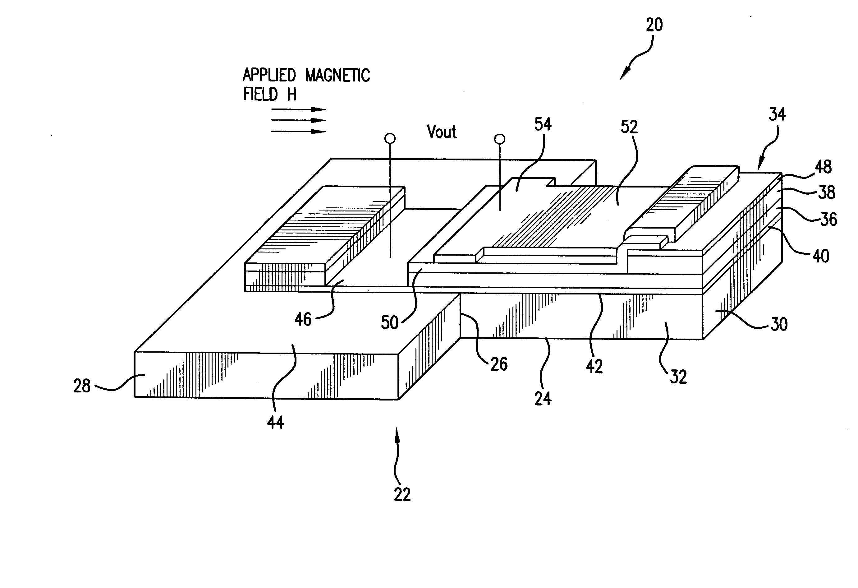
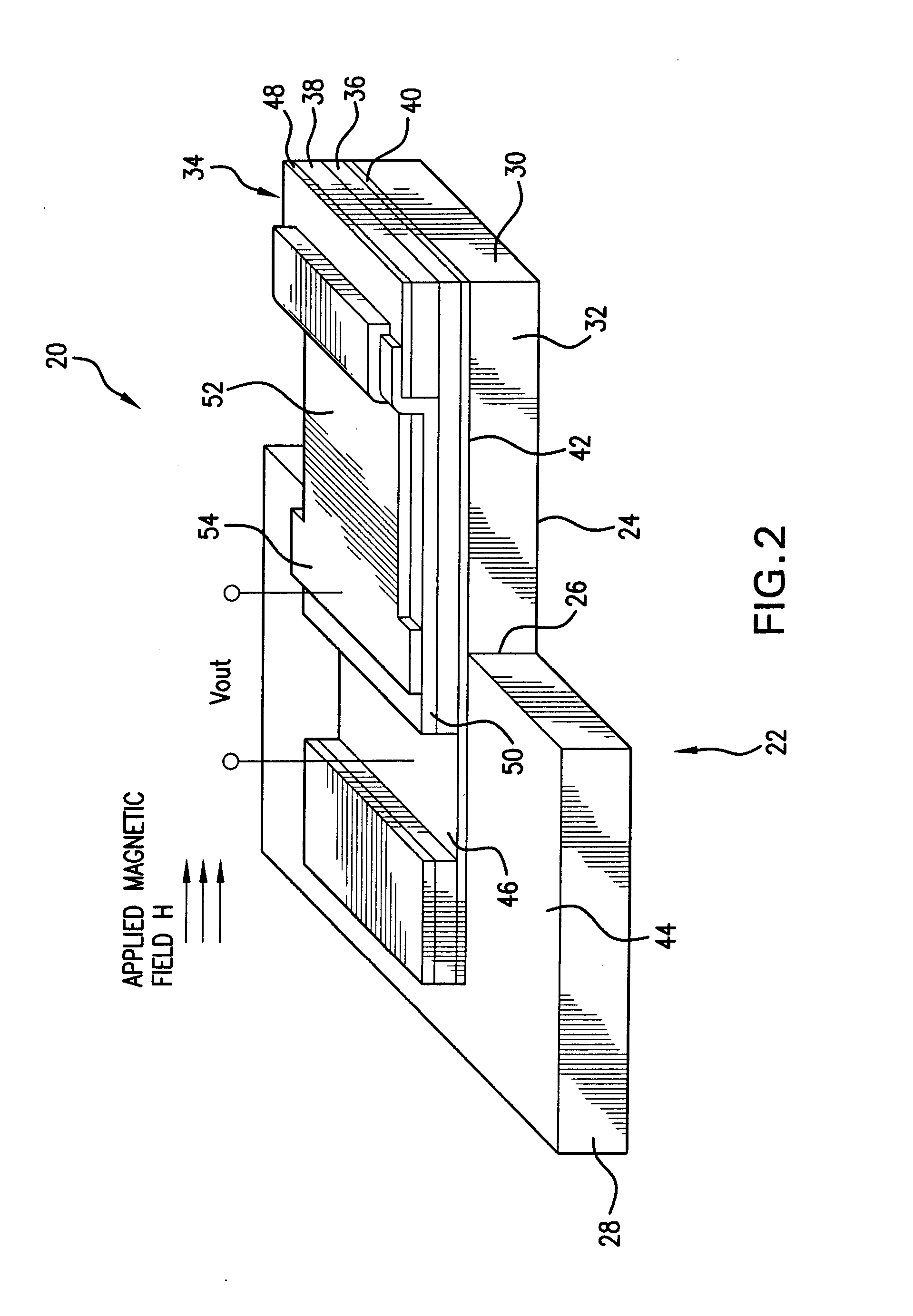
[0062] Referring to FIGS. 2-4, the ultrasensitive magnetoelectric thin film magnetometer 20 of the present system includes a cantilever structure 22 formed from a substrate bulk micromachined element to define a cantilever beam 24 anchored at one end 26 to a cantilever support 28. The cantilever structure is preferably formed from a substrate of Si, SiO2, SiN or any combination thereof. The cantilever structure is formed by etching the bulk substrate about half way through the entire thickness of the substrate (approximately 0.5 mm) through use of any material removal technique, which may be for example wet etching with KOH and diluted HF. The etching step is a rigorous process and may take up to ten hours to form the cantilever structure 22.

[0063] The cantilever beam 24 extends a predetermined length between the end 26 and end 30 thereof which may range from 4 to 50 times the width of the cantilever beam which may range between 10 μm to 1 mm. Alternatively, the width of the cantil...


PUM


Abstract

An ultrasensitive room temperature magnetoelectric thin film magnetometer is fabricated on a cantilever beam and includes an active magnetoelectric multilayer structure having a plurality of thin films formed at a region defined on the cantilever beam. Upon application of a magnetic field, the active magnetoelectric structure generates a corresponding response of an electrical nature which is a measure of a value of the applied magnetic field. The material of the cantilever beam may be removed beneath the active magnetoelectric multilayer structure to form a freestanding modification of the magnetometer with superior sensitivity. The active magnetoelectric multilayer structure is either a bi-layer structure which includes a piezoactive (piezoelectric and / or piezoresistive) thin film deposited in contact with a magnetostrictive thin film or a tri-layer active structure (in the free-standing implementation) including a piezoactive thin film sandwiched between a pair of magnetostrictive thin films.

Description

REFERENCE TO RELATED APPLICATIONS [0001] This utility patent application is based on the Provisional Patent Application Ser. No. 60 / 743,525 filed 17 Mar. 2006.STATEMENT REGARDING FEDERALLY SPONSORED RESEARCH [0002] The invention described herein was developed through research funded by the ONR under contact number N000140110761. The U.S. Government has certain rights to the invention.FIELD OF THE INVENTION [0003] The present system relates to ultrasensitive measurements of magnetic field at room temperature conditions. In particular the concepts elicited in the subject application relate to magnetoelectric thin film magnetometers. [0004] More in particular, the present system is directed to multilayer thin film magnetoselective sensors formed on micromachined cantilevers which exhibit superior performance characteristics due to high magnetoelectric coupling between the piezoelectric (and / or piezoresistive) and magnetostrictive thin films in combination with advantages provided by a ...

Claims


Application Information

Patent Timeline
Patent Type & Authority Applications(United States)
IPC IPC(8): G01R33/02
CPCG01R33/18
Inventor TAKEUCHI, ICHIROWUTTIG, MANFRED R.
Owner MARYLAND UNIV OF
Learn More