Supercharge Your Innovation With Domain-Expert AI Agents!

Optical Storage Interface Aparatus

Inactive Publication Date: 2007-11-01
KONINKLIJKE PHILIPS ELECTRONICS NV
View PDF6 Cites 2 Cited by
  • Summary
  • Abstract
  • Description
  • Claims
  • Application Information

AI Technical Summary

Benefits of technology

[0009] Another advantage of the invention relates to the following aspects. A slider of the type that is used in magnetic hard drives relies on an air-bearing surface with positive and negative pressure pockets. These pressure pockets build up pressure on which the slider floats so that there is an air gap between the slider and a disk, which is spinning. In practice, there will be dust, debris and other contamination in the pressure pockets. This can be an important reason for failure, in particular in an ordinary environment. The air gap may become too large or too narrow, which will affect readout or recording of data. The slider may even hit the disk. In that case, a thin leaf spring suspension, to which the slider is generally coupled, may get damaged. This is a major incident. Any readout or recording of data will no longer be possible until repair.
[0010] In accordance with the aforementioned aspect of the invention, the spot-forming lens is positioned with respect to an optical information carrier on the basis of a gap indication signal. The invention does not rely on pressure pockets to achieve a relatively small air gap. Instead, the invention uses an active control that seeks to maintain a constant, relatively small air gap. It has been observed that such an active control is less sensitive to dust, debris, and other contamination than a slider-based solution as in the prior art described hereinbefore. This further contributes to reliable and robust data readout and data recording. Furthermore, data readout or data recording can take place in a less protective environment compared with a slider-based solution as in the prior art. Protection against dust, debris, and other contamination generally involves costs. The aforementioned active control thus allows cost savings with regard to such protection. These cost savings will generally outweigh any additional costs associated with additional hardware or software, or both, which may be required compared with a slider-based solution.
[0011] These and other aspects of the invention will be described in greater detail hereinafter with reference to drawings.

Problems solved by technology

Without close proximity, the spot size increases and the total energy available for coupling into the recording layer decreases due to evanescent decay.

Method used


Image

  • Optical Storage Interface Aparatus
  • Optical Storage Interface Aparatus
  • Optical Storage Interface Aparatus

Examples


Embodiment Construction

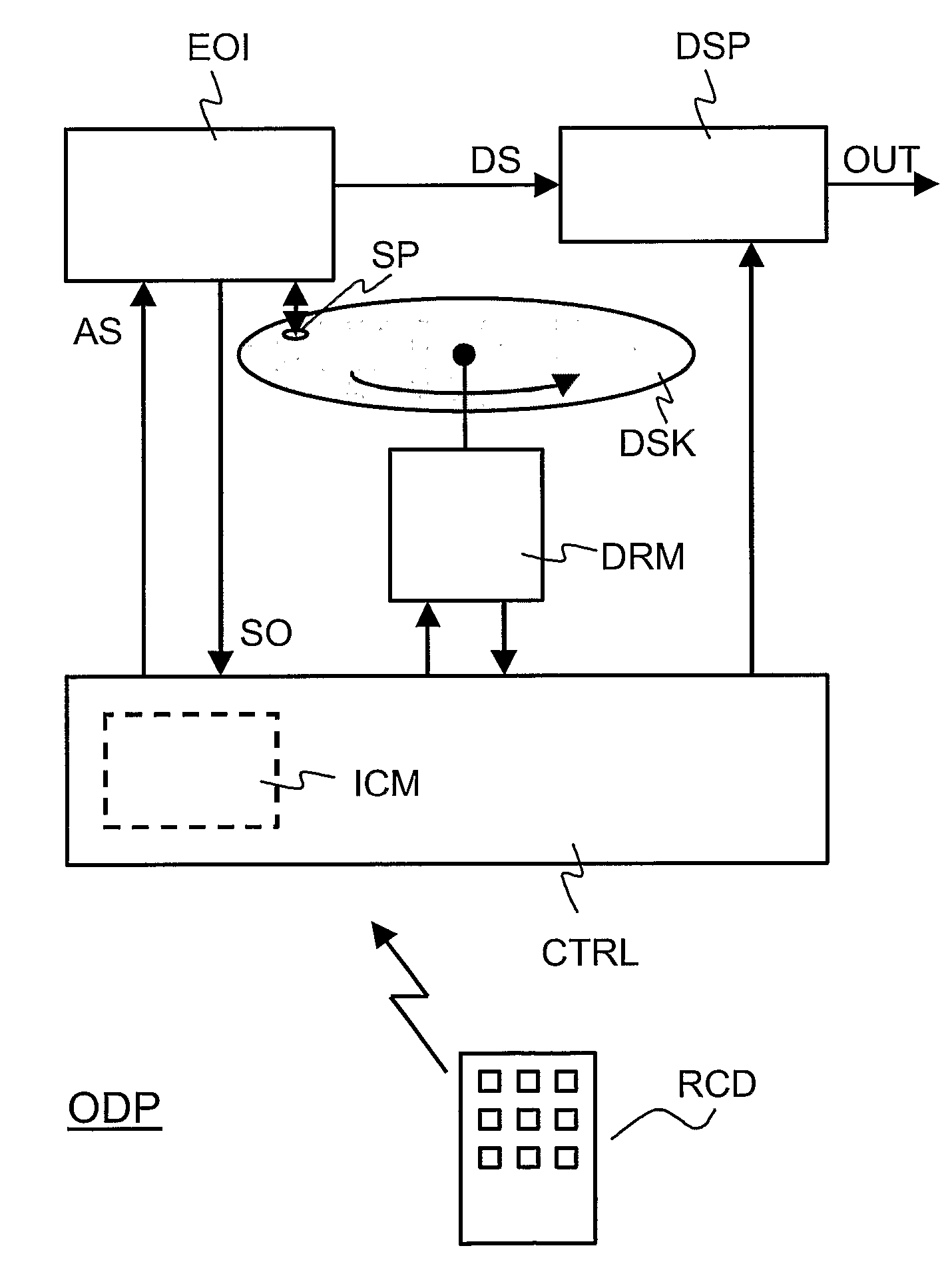
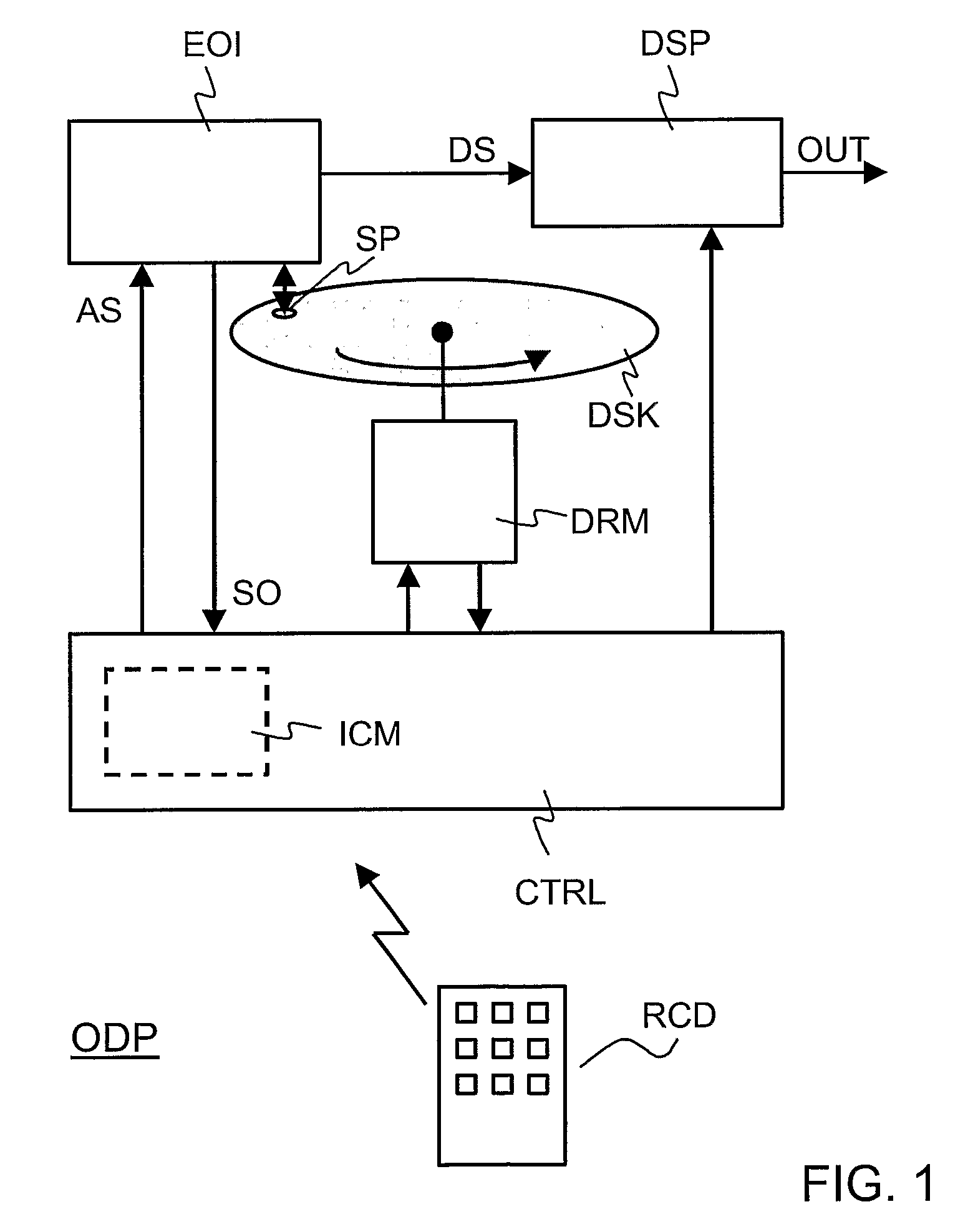
[0021]FIG. 1 illustrates an optical disk player ODP. The optical disk player ODP comprises an electro-optical interface EOI, a data signal processor DSP, a disk-rotation motor DRM, and a controller CTRL. The optical disk player ODP may further comprises a remote control device RCD. It is assumed that a disk DSK is present in the optical disk player ODP. The controller CTRL may be in the form of, for example, a programmable processor that comprises a program memory. In that case, one or more software modules, which are stored in the program memory, define operations, which the controller CTRL carries out.

[0022] The optical disk player ODP basically operates as follows. Let it be assumed that a user presses a play button on the remote control device RCD. The remote control device RCD sends a wireless signal to the controller CTRL. The controller CTRL interprets this wireless signal as a play command and, in response, causes the disk-rotation motor DRM to make the disk DSK rotate. The...


PUM


Abstract

In an optical storage interface apparatus, a spot-forming lens projects a light spot on an optical information carrier in response to a light beam from a light source. There is an air gap (AG) between the spot-forming lens and the optical information carrier. A gap detector (PHD2) provides a gap indication signal (GIS) that varies with the air gap (AG) in accordance with a gap indication transfer function (F). A lens-positioning arrangement (CTRL, ACT) positions the spot-forming lens with respect to the optical information carrier on the basis of the gap indication signal (GIS). The lens-positioning arrangement (CTRL, ACT) comprises a compensator (CMP) for compensating nonlinearity in the gap indication transfer function (F). A suitable compensation transfer function (G) can be established on the basis of servo control loop measurements. Accordingly, compensation can be provided without any prior knowledge of the gap indication transfer function (F).

Description

FIELD OF THE INVENTION [0001] An aspect of the invention relates to an optical storage interface apparatus. The optical storage interface apparatus may be, for example, a digital versatile disk (DVD) player, which can read data from a DVD disk, or a DVD recorder, which can also write data onto a DVD disk. The optical storage interface apparatus may comprise, for example, a near-field optical system, which allows high density data readout and storage. Other aspects of the invention relate to a method of controlling an optical storage interface, and a computer program product for an optical storage interface. BACKGROUND OF THE INVENTION [0002] The article entitled “Near-Field Optics: A New tool for Data Storage” by Tom D. Milster, IEEE proceedings, Vol. 88, No. 9, September 2000, pages 1480-1490, describes that near-field optical systems use evanescent energy to produce extremely small optical spots. Two practical implementations that use evanescent energy are aperture probes and soli...

Claims


Application Information

Patent Timeline
IPC IPC(8): G11B7/00G11B7/135
CPCG11B7/1387G11B7/0908G11B7/09G11B7/095
Inventor LEE, JUILZIJP, FERRY
Owner KONINKLIJKE PHILIPS ELECTRONICS NV
Features
  • R&D
  • Intellectual Property
  • Life Sciences
  • Materials
  • Tech Scout
  • Unparalleled Data Quality
  • Higher Quality Content
  • 60% Fewer Hallucinations
Learn More