Sensor and guide wire assembly

a technology of sensor guide wire and assembly, which is applied in the direction of guide wires, sensors, medical science, etc., can solve the problems of limited core wire diameter, jeopardizing compatibility, and inability to increase outer diameter, so as to improve the manoeuvrability of sensor guide wire and reduce the risk of electrical failure

Inactive Publication Date: 2007-11-01
ST JUDE MEDICAL COORDINATION CENT
View PDF17 Cites 113 Cited by
  • Summary
  • Abstract
  • Description
  • Claims
  • Application Information

AI Technical Summary

Benefits of technology

[0009] A general object of the present invention is to provide an improved design for a sensor and guide wire assembly, which enhances the manoeuvrability of the sensor guide wire and, at the same time, reduces the risk of electrical failure of the signal transmitting cable(s) arranged in the sensor guide wire.
[0012] From one aspect, a polymer layer can be regarded as a replacement for a proximal coil spring, and has the advantage that it easily can be made thinner than a conventional coil spring, thereby providing the possibility to increase the outer diameter of the core wire portion enclosed by this polymer layer. As previously discussed, a larger core wire diameter implies a higher torqueability and thereby improved manoeuvrability of the sensor guide wire. On the other hand, if the core wire diameter is left unchanged, more space can be provided for the signal transmitting cables, which, in turn, may involve the possibility of taking different kinds of measures to protect the electrical signal cables. The thickness of the electrical insulation surrounding the cables can, for example, be increased.
[0013] Further, in contrast to a coil spring, which inherently is permeable to bodily fluids such as blood, a polymer layer can easily be made essentially impermeable to bodily fluids. An impermeable outer layer entails the advantage that the insulating requirements on the thin signal transmitting cables can be reduced as no electrically conductive fluid will be present between the cables.

Problems solved by technology

The core wire diameter is, however, limited by the outer diameter of the sensor guide wire, and this outer diameter cannot be increased without jeopardizing the compatibility with other interventional devices, such as different kinds of catheters which are threaded over the sensor guide wire in order to treat the stenosis that was diagnosed by the sensor and guide wire assembly.
Ultimately, the diameters of all interventional devices are, however, apparently limited by the diameters of the narrow arteries of the peripheral coronary tree—if anything there is consequently a desire to reduce the outer diameter of a sensor guide wire.
Damage on an electrical signal cable or, perhaps more likely, on the electrical insulation surrounding the cable can lead to unreliable performance or even short-circuit of the sensor.
The proximal coil spring is provided for improving the manoeuvrability of the sensor guide wire, but may also put further limitations on the maximum dimensions of a core wire disposed therein.

Method used


Image

  • Sensor and guide wire assembly
  • Sensor and guide wire assembly
  • Sensor and guide wire assembly

Examples


first embodiment

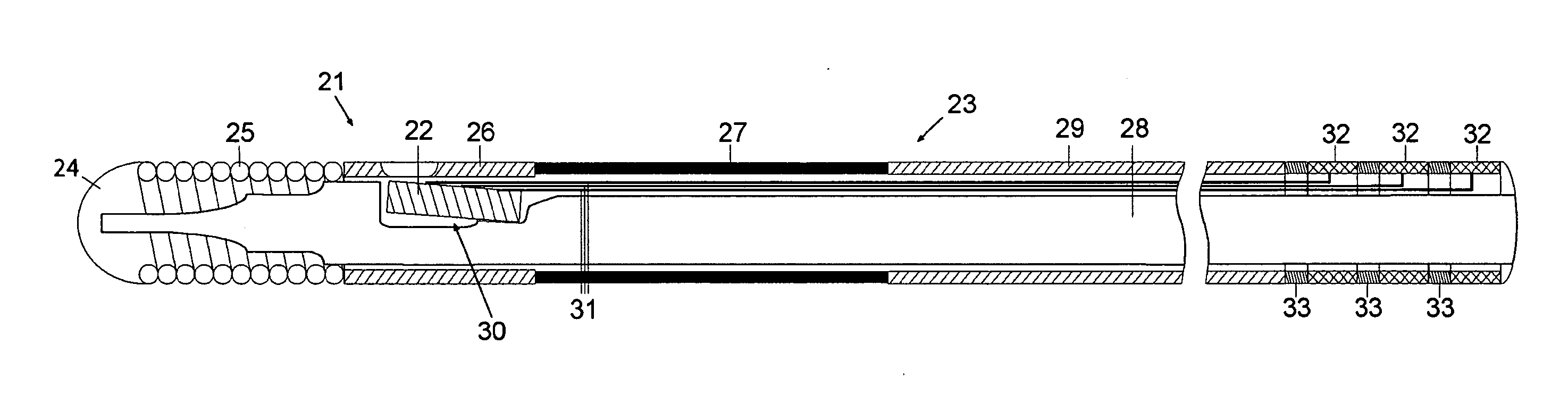
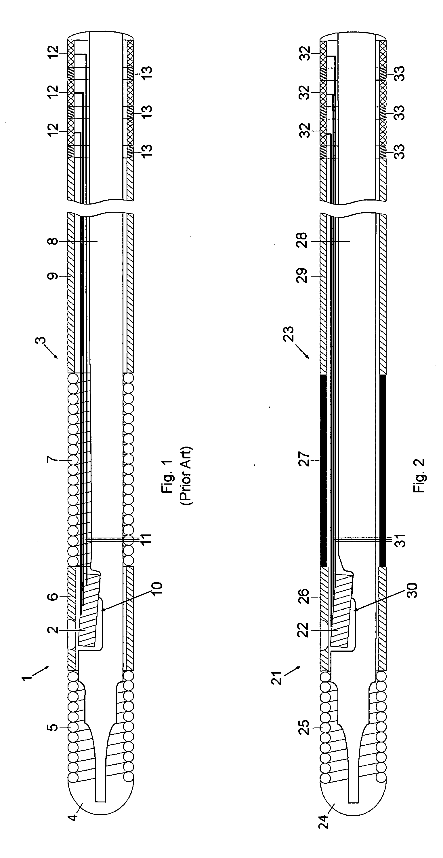
[0024] In FIG. 2 a sensor and guide wire assembly 21 according to the present invention is schematically illustrated. The sensor and guide wire assembly 21 comprises a sensor element 22, which is arranged in a distal portion of a sensor guide wire 23. More specifically, the sensor guide wire 23 comprises a distal tip 24, a distal coil spring 25, a jacket or sleeve 26, a core wire 28, and a proximal tube 29. The distal coil spring 25 is attached to the distal tip 24 and extends to the jacket 26, which serves as a housing for the sensor element 22. Unlike in a conventional design of a sensor guide wire, an example of which is shown in FIG. 1, the sensor guide wire 23 comprises further a polymer layer 27, which extends between the jacket 26 and the proximal tube 29. The distal coil spring 25, the jacket 26, the polymer layer 27 and the proximal tube 29 are all tubular members having essentially equal outer diameters and surrounding different consecutive portions of the core wire 28. Th...

second embodiment

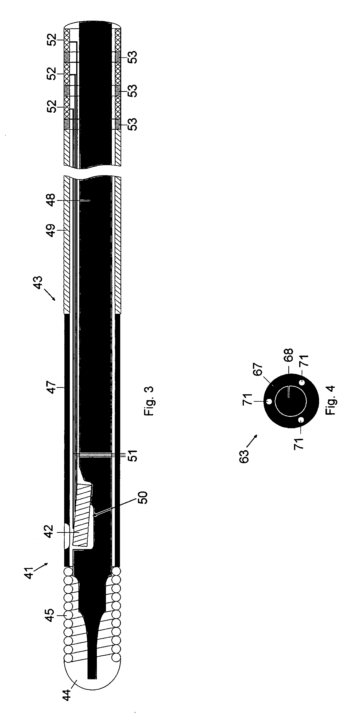
[0028] In FIG. 3 a sensor and guide wire assembly 41 according to the present invention is schematically illustrated. The sensor and guide wire assembly 41 comprises a sensor element 42, which is arranged in a distal portion of a sensor guide wire 43. More specifically, the sensor guide wire 43 comprises a distal tip 44, a distal coil spring 45, a polymer layer 47, a core wire 48, and a proximal tube 49. The distal coil spring 45 is attached to the distal tip 44 and extends to the polymer layer 47. In this embodiment, the sensor element 42 is enclosed by the polymer layer 47, which also serves as a housing for the sensor element 42. The distal coil spring 45, the polymer layer 47 and the proximal tube 49 are all tubular members having essentially equal outer diameters and surrounding different consecutive portions of the core wire 48. The sensor element 42 is mounted in a recess 50 in a distal portion of the core wire 48, and is through a window in the polymer layer 47 in communicat...

fourth embodiment

[0030] a sensor and guide wire assembly according to the present invention comprises a sensor guide wire 63 having a cross-section which is schematically illustrated in FIG. 4. The sensor guide wire 63 comprises a core wire 68, three signal transmitting cables 71 and a polymer layer 67. Rather than being arranged around the signal transmitting cables 71—as in the previous embodiments—, the polymer layer 67 has been applied as a coating 67 on a section of the core wire 68, with the three signal cables 71 being embedded in the polymer coating 67. With this arrangement, the signal cables 71 can be produced without a separate insulating layer on each signal cable 71, because the polymer coating will electrically insulate each of the signal transmitting cables 71. When the signal cables are embedded in a polymer layer, the diameter of the core wire can be increased in comparison with an arrangement where a polymer layer in the form of a tubing surrounds the signal cables. The stiffness, ...


PUM


Abstract

A sensor and guide wire assembly (21; 41) for intravascular measurements of a physiological variable in a living body, comprises a sensor element (22; 42) and a sensor guide wire (23; 43) comprising a core wire (28; 48) and at least one signal transmitting cable (31; 51) connected to the sensor element, wherein a polymer layer (27; 47) is provided which encloses a portion of the core wire and the at least one signal transmitting cable.

Description

FIELD OF THE INVENTION [0001] The invention relates generally to sensors mounted on guide wires for intravascular measurements of physiological variables in a living body, and in particular to the design of such sensor guide wires. BACKGROUND OF THE INVENTION [0002] Sensor and guide wire assemblies in which a sensor, adapted for measurements of physiological variables in a living body, such as blood pressure and temperature, is mounted at a distal portion of a guide wire are known. [0003] For example, the U.S. Pat. No. Re. 35,648, which is assigned to the present assignee, and whose entire contents are incorporated herein by reference for details as to sensors, guide wires, and associated techniques, discloses a sensor and guide wire assembly comprising a sensor element, an electronic unit, signal transmitting cables connecting the sensor element to the electronic unit, a flexible tube having the signal cables and the sensor element disposed therein, a solid metal wire, and a coil a...

Claims


Application Information

Patent Timeline
Patent Type & Authority Applications(United States)
IPC IPC(8): A61B5/02
CPCA61B5/0215A61M25/09A61B5/6851
Inventor SMITH, LEIFMALMBORG, PAR VONDURING, ERIK
Owner ST JUDE MEDICAL COORDINATION CENT
Why Eureka
Try Eureka