Integrated Parallel Peltier/Seebeck Element Chip and Production Method Therefor, Connection Method

a technology of parallel peltier/seebeck element and production method, which is applied in the manufacture/treatment of thermoelectric devices, electrical apparatus, and semiconductor devices, etc., can solve the problems of potential difference between the two conductors, mechanical energy or chemical energy taking out technique not yet developed to a practical level, and still remains a considerable long way to go. , to achieve the effect of fast equalization temperature and superior thermal conductivity

Active Publication Date: 2007-11-08
MEIDENSHA ELECTRIC MFG CO LTD +1
View PDF3 Cites 39 Cited by
  • Summary
  • Abstract
  • Description
  • Claims
  • Application Information

AI Technical Summary

Benefits of technology

[0014] According to still another aspect of the present invention, in the integrated parallel Peltier Seebeck element chip fabricating process a plurality of the thermal conduction terminal portions each connected by ohmic contact with the first and second conducive members bared in a lower surface of the integrated parallel Peltier Seebeck element chip are all joined with a material which is thermally conductive and electrically insulating so that the thermal conduction terminal portions are electrically insulated from one another, and arranged to quickly equalize temperatures of all the thermal conduction terminal portions of the first and second conductive members. As the material having a superior thermal conductivity and an electric insulating property in a joint surface, it is possible to use material so processed to have an electrically insulating surface by alumite treatment, for example.
[0015] According to still another aspect of the present invention, the integrated parallel Peltier Seebeck

Problems solved by technology

However, the development of clean energy is still in a nascent stage, and there still remains a considerably long way to go until the use as a substitute for fossil fuel and atomic energy.
Although thermal energy exists inexhaustibly in the natural world, on the other hand, the technique to take out the thermal energy in the form of mechanical energy or chemical ener

Method used


Image

  • Integrated Parallel Peltier/Seebeck Element Chip and Production Method Therefor, Connection Method
  • Integrated Parallel Peltier/Seebeck Element Chip and Production Method Therefor, Connection Method
  • Integrated Parallel Peltier/Seebeck Element Chip and Production Method Therefor, Connection Method

Examples


Embodiment Construction

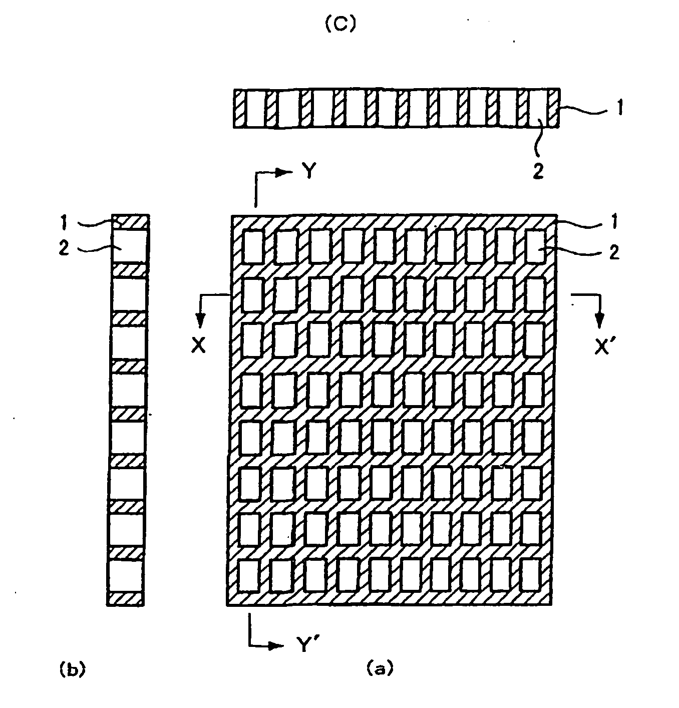
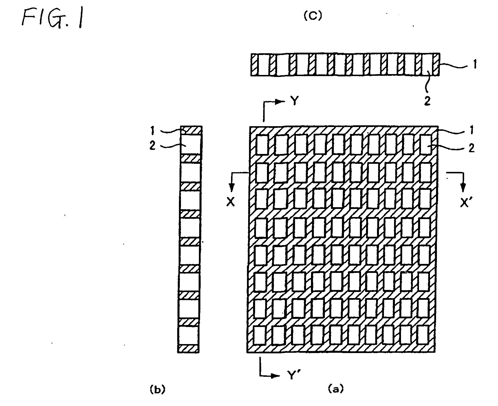
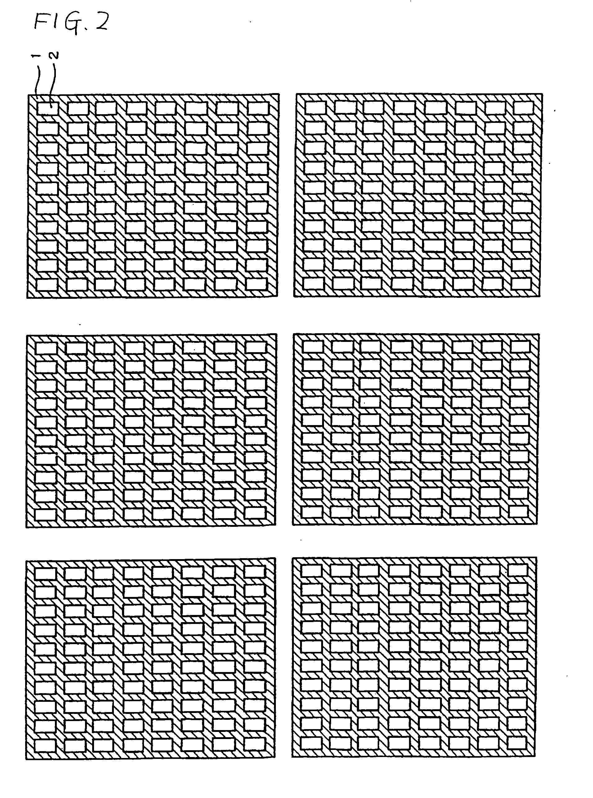
[0034] The following is explanation on one example of a fabrication process or method of fabricating an Integrated Parallel Peltier Seebeck Elements (IPPS) Chip (hereinafter abbreviated to “IPPS chip”), with reference to FIGS. 1˜8.

[0035] First, an amorphous silicon wafer is produced by forming, on a very thin heat resistant plastic base plate, an amorphous silicon (noncrystalline silicon) layer having a uniform thickness from several micron meters to 5 millimeters or to ten-plus-several millimeters, for example, according to usage, by vacuum evaporation, sputtering, plasma CVD (Chemical Vapor Deposition) etc. In the case of plasma CVD, for example, an amorphous silicone wafer of a uniform thickness as mentioned before is produced by growing an amorphous silicon layer on a base plate by decomposition of silane (SiH4) and / or silane disilane (SiH6) by glow discharge.

[0036] Alternatively, a polysilicon (polycrystalline silicon) wafer much higher in a carrier mobility of electrons and ...


PUM


Abstract

First and second conductive members having different Seebeck coefficients are formed on an insulating substrate. The first and second conductive members are connected by ohmic contact, and the surfaces connected by ohmic contact are covered with a material sheet having a superior heat conductivity and an electric insulating property in the junction surface, such as an aluminum sheet formed with surfaces provided with electric insulating property by alumite treatment or the like. On the opposite side, bonding wires are connected with the first and second conductive members by ohmic contact. The bonding wires are insulated from one another, and used as output terminals of an integrated parallel Peltier Seebeck element chip. The thus produced integrated parallel Peltier Seebeck element chips are connected by one or more serial or parallel cables, to form energy conversion apparatus from electricity to heat and thermal energy transfer apparatus.

Description

TECHNICAL FIELD [0001] The present invention relates to a fabricating process for producing an integrated parallel Peltier Seebeck element chip for conversion from energy in one form to energy in another form or transfer of heat energy, an integrated parallel Peltier Seebeck element chip produced by this fabricating process, a connecting process of connecting a plurality of integrated parallel Peltier Seebeck element chips, and an integrated Peltier Seebeck panel or sheet in which a plurality of the integrated parallel Peltier Seebeck element chips are connected. Moreover, the present invention relates to heat energy electric energy direct conversion system and heat energy transfer system produced by the integrated parallel Peltier Seebeck element chip. BACKGROUND ART [0002] Currently, in the world, energy is used mostly in the form of fossil fuel, atomic power, water energy etc. in an irreversible manner. Especially, the consumption of fossil fuel is a factor for accelerating globa...

Claims


Application Information

Patent Timeline
IPC IPC(8): H01L35/28
CPCH01L27/16H01L35/34H01L2924/0002H01L2924/00H10N19/00H10N10/01
Inventor KONDOH, YOSHIOMI
Owner MEIDENSHA ELECTRIC MFG CO LTD
Why Eureka
Try Eureka