Air-fuel ratio control device for internal combustion engine

a technology of air-fuel ratio and control device, which is applied in the direction of electrical control, process and machine control, instruments, etc., can solve the problems of limited heat impact on the downstream osub>2 /sub>sensor, abnormal high exhaust gas temperature during use, and low poisoning

Inactive Publication Date: 2007-11-15
MITSUBISHI ELECTRIC CORP
View PDF6 Cites 7 Cited by
  • Summary
  • Abstract
  • Description
  • Claims
  • Application Information

AI Technical Summary

Benefits of technology

[0012]The invention aims to address the above problems, and it is an object thereof to provide an air-fuel ratio control device for an internal combustion engine that can detect a deteriorated purification state of a catalyst without delay, and that can rapidly restore the purification state after rich or lean control is completed. This is achieved by setting a filter process constant for a downstream air-fuel ratio sensor output to be smaller when rich or lean control are performed.

Problems solved by technology

However, the upstream O2 sensor is exposed to high exhaust temperatures and poisoned by various kinds of toxic substance, and thus the output characteristics of the O2 sensor vary substantially.
The impact of heat on the downstream O2 sensor is limited since the exhaust temperature is low at the downstream side of the catalytic converter, and poisoning is also low since the catalyst traps the various kinds of toxic substance.
However, there may be occasions when the exhaust gas temperature becomes abnormally high during use due to a cause like misfire.
Moreover, even under normal usage conditions, if the vehicle's mileage reaches tens of thousands of miles, the oxygen storage capacity of the catalyst will gradually reduce due to age deterioration.
However, as the catalyst deteriorates, the filter action also reduces, and thus variation in the air-fuel ratio of the upstream side is transmitted to the downstream side causing the stability of the downstream O2 sensor output to worsen.
However, in the case that the stability of the downstream O2 sensor output has worsened due to catalyst deterioration, the stability of the air-fuel ratio control using the upstream O2 sensor is also impaired.
At such times, the amount of oxygen in the catalyst reaches the upper / lower limit of the oxygen storage capacity and the atmosphere of the catalyst cannot be maintained at the stoichiometric air-fuel ratio, whereby purification capability drops substantially.
However, in known air-fuel ratio control devices in which the air-fuel ratio control is performed using the filter processed output of the downstream O2 sensor, there is a delay in detecting the purification state of the catalyst, which leads to a delay in restoring purification capability.

Method used


Image

  • Air-fuel ratio control device for internal combustion engine
  • Air-fuel ratio control device for internal combustion engine
  • Air-fuel ratio control device for internal combustion engine

Examples


first embodiment

[0035]FIG. 3 shows the configuration of an air-fuel ratio control device for an internal combustion engine according to a first embodiment of the invention. In the figure, an air flow meter 3 is disposed in an intake passage 2 of an internal combustion engine body 1. The air flow meter 3 directly measures the intake air quantity, and has a built-in hot-wire and generates an analog voltage output signal that is proportionate to the intake air quantity. The output signal is supplied to an A / D converter 101 with built-in multiplexer, which is included in a control circuit 10. A distributor 4 is provided with a crank angle sensor 5 and a crank angle sensor 6. The crank angle sensor 5 generates a pulse signal indicating detection of a reference position when the shaft of the distributor 4 is at a point corresponding to, for example, each 720 degrees crank angle. The crank angle sensor 6 generates a pulse signal indicating detection of a reference position when the shaft of the distributo...

second embodiment

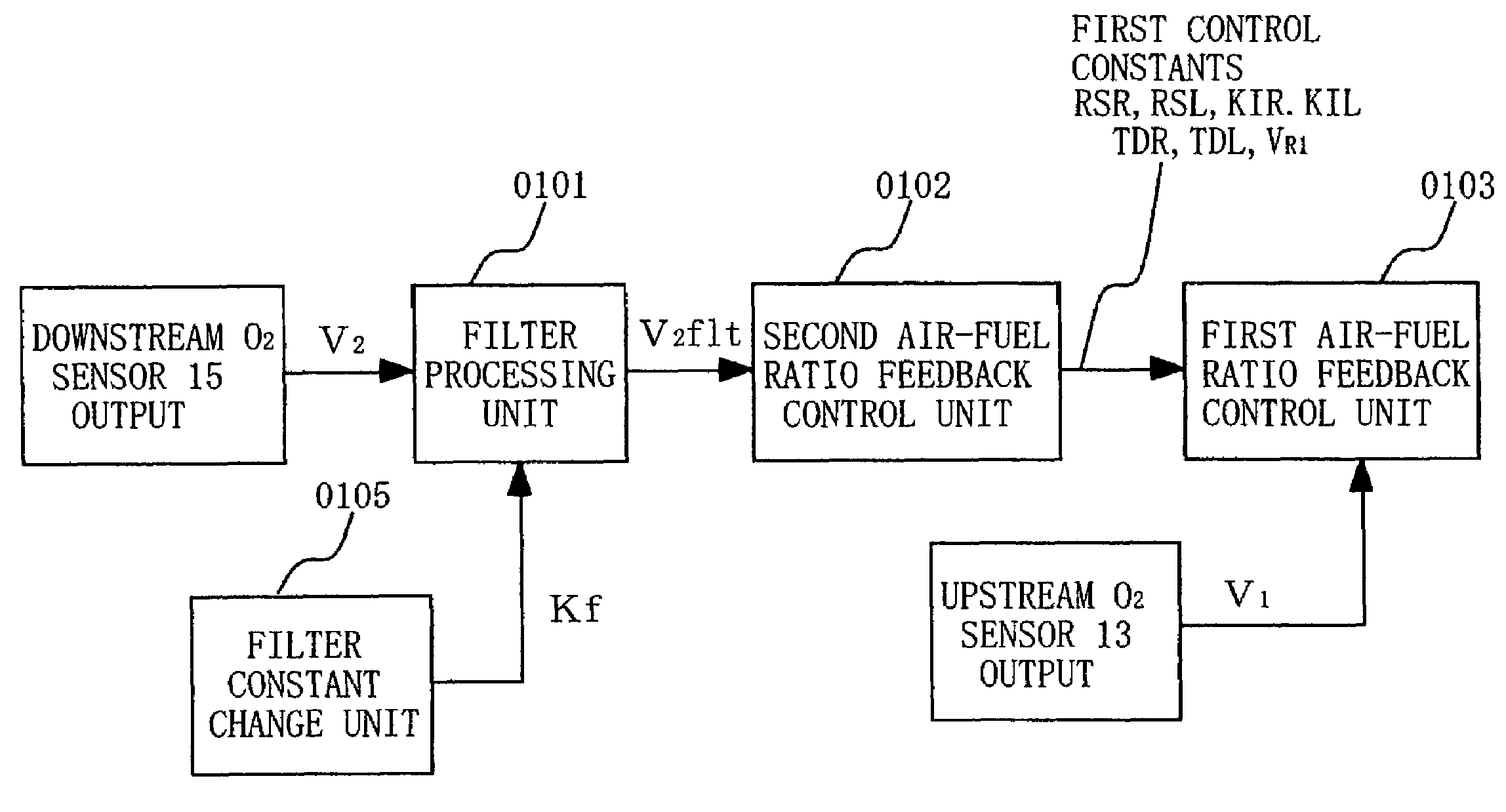
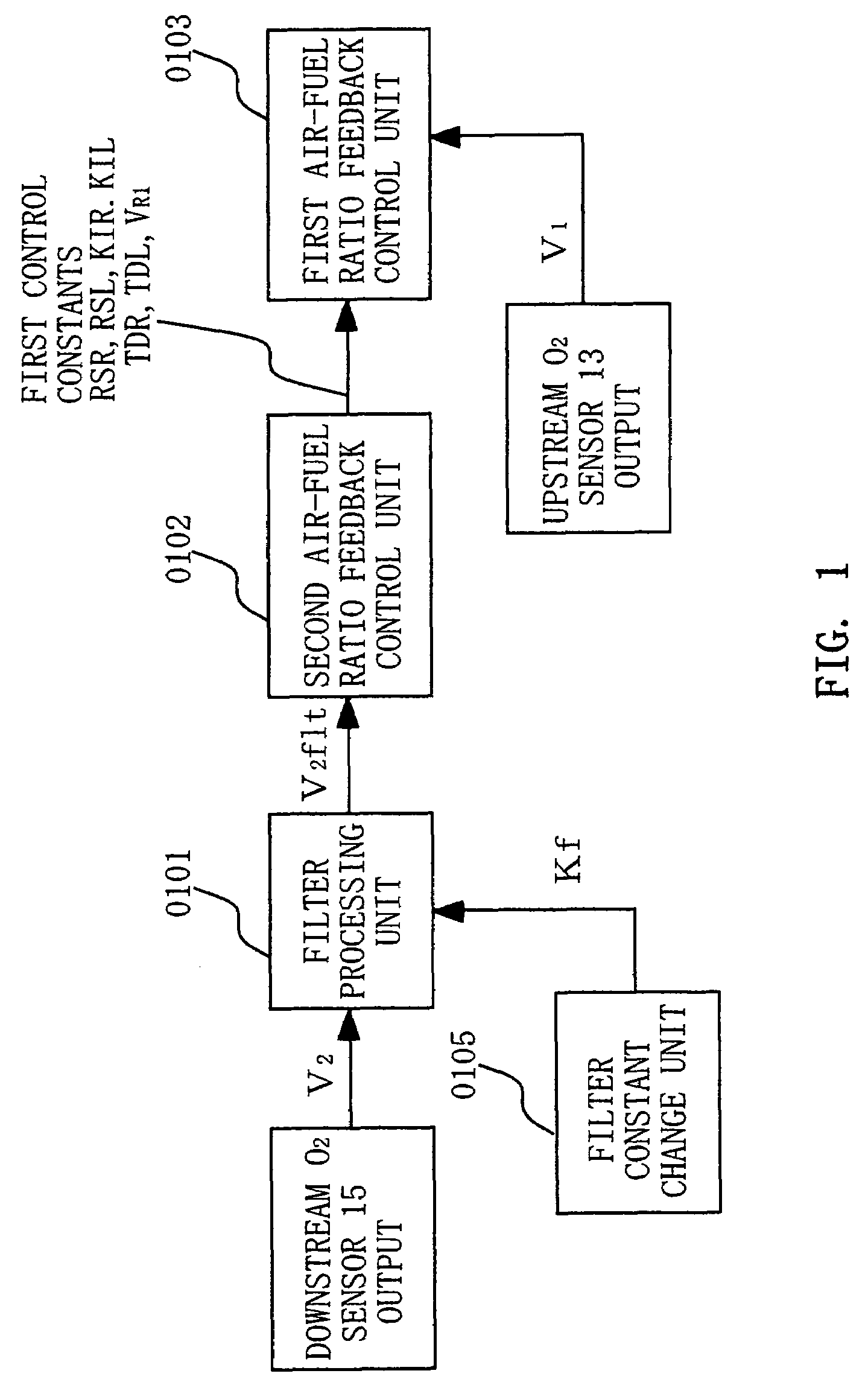
[0099]It is sufficient if the downstream O2 sensor is a sensor that can detect the purification state of the upstream catalyst. Since a linear air-fuel ratio sensor, a NOx sensor, an HC sensor, a CO sensor or the like can also control the purification state of the catalyst, the same effects as above can be achieved if such sensors are used. The upstream O2 sensor may be a linear O2 sensor that has linear output characteristics with respect to changes in the air-fuel ratio. In this case, since the upstream air-fuel ratio can be controlled in a similar manner to a λ O2 sensor, the same effects as above can be achieved. The second air-fuel ratio feedback control unit described above is configured from a proportional calculation and an integral calculation. However, even if the configuration also includes a differential calculation, the feedback control can be performed and the same effects as above can be achieved.

[0100]The, second air-fuel ratio feedback control unit described above i...


PUM


Abstract

An air-fuel ratio control device for an internal combustion engine can detect the deteriorated purification state of a catalyst without delay after completion of rich or lean control, and can rapidly restore the purification state. A filter process constant for a downstream O2 sensor output is set smaller when rich or lean control are performed, thus allowing detection of the deteriorated purification state of the catalyst without delay. After the rich or lean control is completed, a dual O2 control system is used to rapidly restore the purification state. Further, the impact of downstream O2 sensor output variation when the catalyst is deteriorated can be suppressed, and stability of the dual O2 control system can be maintained.

Description

BACKGROUND OF THE INVENTION[0001]1. Field of the Invention[0002]The present invention relates to an air-fuel ratio control device for an internal combustion engine that is provided with air-fuel ratio sensors at upstream and downstream sides of a catalyst. The air-fuel ratio control device performs air-fuel ratio control based on the output of air-fuel ratio sensors at the upstream and downstream side.[0003]2. Description of the Related Art[0004]Normally, a three-way catalyst is provided in an exhaust passage of an internal combustion engine to simultaneously purify HC, CO, and NOx contained within the exhaust gas. With this catalyst, the purification rate of each one of HC, CO and NOx is increased in the vicinity of the stoichiometric air-fuel ratio. Accordingly, normally, an air-fuel ratio sensor is provided at the upstream side of the catalyst and the air-fuel ratio controlled to be in the vicinity of the stoichiometric air-fuel ratio. Here, a structure will be explained in which...

Claims


Application Information

Patent Timeline
Patent Type & Authority Applications(United States)
IPC IPC(8): F01N3/00
CPCF01N9/00F01N2560/025F01N2560/14F01N2900/0422Y02T10/47F02D41/1441F02D41/1488F02D2041/1432F02M69/043F02D41/0235Y02T10/40
Inventor TAKUBO, HIDEKI
Owner MITSUBISHI ELECTRIC CORP
Why Eureka
Try Eureka