Rotary fiberization process for making glass fibers, an insulation mat, and pipe insulation

a technology of rotary fiberization and glass fiber, which is applied in the field of tubular glass fiber pipe insulation making process, can solve the problems of increasing the difficulty of maintaining the energy balance required by the process to produce such glass fiber, increasing the energy required for centrifuge the molten glass fiber into fibers, and reducing the size and length. , the effect of high localized temperature increas

Active Publication Date: 2007-11-15
JOHNS MANVILLE CORP
View PDF47 Cites 10 Cited by
  • Summary
  • Abstract
  • Description
  • Claims
  • Application Information

AI Technical Summary

Benefits of technology

[0009] The annular fluid attenuation region is spaced radially outward from the spinner disc sidewall and extends from the upper edge portion down through the mid-portion of the annular sidewall of the spinner. An attenuation fluid is forcefully emitted from above into the annular fluid attenuation region. The forcefully emitted attenuation fluid attenuates the primary glass fibers introduced into the annular fluid attenuation region into lesser diameter glass fibers having diameters as low as 3 microns (typically between 5 microns and 8 microns) and directs those lesser diameter glass fibers downward away from the spinner disc in a generally tubular veil of the lesser diameter glass fibers and fiber networks formed from a portion of the lesser diameter glass fibers. In addition to the attenuation fluid, oxygen can be injected from above into and combusted in the annular fluid attenuation region to effect a relatively high localized temperature increase in a portion of the annular fluid attenuation region where there are high rates of shear attenuating the primary glass fibers into the lesser diameter glass fibers.
[0010] Preferably, the lesser diameter glass fibers of the tubular veil of lesser diameter glass fibers are dispersed by forcefully applying fluid onto the veil to reduce in size and length the fiber networks formed from the lesser diameter glass fibers. This dispersion of the lesser diameter glass fibers can be accomplished, at least in part, by forcefully emitting the attenuating fluid into the annular fluid attenuation region at alternating angles and / or in a non-uniform pattern. This dispersion of the lesser diameter glass fibers can also be accomplished, at least in part, by forcefully applying a binder and / or other fluid to the lesser diameter glass fibers of the tubular veil of lesser diameter glass fibers from within and / or outside of the tubular veil at a location or locations beneath the annular fluid attenuation region. Furthermore, all of these methods of fiber dispersion can be utilized together to attain the desired amount of lesser diameter fiber dispersion and can be combined with the use of a forming tube configured to effect fiber dispersion.

Problems solved by technology

However, when making a glass fiber mat containing fibers ranging between 5 and 8 microns for forming tubular pipe insulation with a rotary fiberization process, a number of processing problems are encountered as illustrated by the following examples.
For the weight range of the mats that are used to make tubular pipe insulation and the downstream speed limitations of pipe insulation production processes, the pull rate per rotary fiberizer used to make the relatively large diameter glass fibers in the quantities required to be collected into such mats is relatively low when compared to the pull rates normally encountered in commercial rotary glass fiberization processes and can increase the difficulty of maintaining the energy balance required by the process to produce such glass fibers.
The elevated glass viscosity of the molten glass used to make glass fibers for pipe insulation, compared to the glass viscosities typically used in other commercial rotary glass fiberization processes, increases the energy required to centrifuge the molten glass into fibers and limits the molten glass throughput through conventionally sized spinner fiberization holes.
Furthermore, spinner alloy service temperature limitations inhibit raising the operating temperatures of the process as a means to compensate for and reduce this elevated viscosity.
Another issue that must be overcome when utilizing a rotary fiberization process is the networking of the glass fibers where the glass fibers produced by the process become entangled together prior to their collection into a mat to the extent that the process and mat produced by the process are adversely affected by the networked glass fibers.
The accumulation of the glass fibers produced in the process into large networks of glass fibers can adversely affect the application of binder to the glass fibers and the collection of the glass fibers into a mat having a generally uniform fiber weight distribution and tear strength.
When a mat containing networks of glass fibers that are too large is pulled apart during the process to separate the mat into mat sections that are successively wound about mandrels to form tubular pipe insulation, the networked glass fibers can adversely affect the uniform tearing of the mat so that the mat sections formed do not have generally straight feathered leading and trailing mat section edges and can form fibrous stringers extending beyond the leading and trailing edges of the mat sections for distances that create processing and / or finished product problems.
For example, the presence of these stringers can adversely affect the winding the mat sections about the mandrels to form a tubular pipe insulation product through their entanglement with the winding apparatus and can adversely affect the appearance of the outer surface of the finished tubular pipe insulation product by making the outer surface of the product irregular.
Furthermore, where the separated mat sections have relatively thick and / or ragged leading and trailing edges rather than generally straight feathered edges, the spiral winding of a mat section onto a mandrel to form a tubular pipe insulation product can leave a longitudinally extending ridge on the internal surface of the product that adversely affects the product's insulating properties and / or a longitudinally extending ridge on the external surface of the product that adversely affects the product's appearance.

Method used


Image

  • Rotary fiberization process for making glass fibers, an insulation mat, and pipe insulation
  • Rotary fiberization process for making glass fibers, an insulation mat, and pipe insulation
  • Rotary fiberization process for making glass fibers, an insulation mat, and pipe insulation

Examples


Embodiment Construction

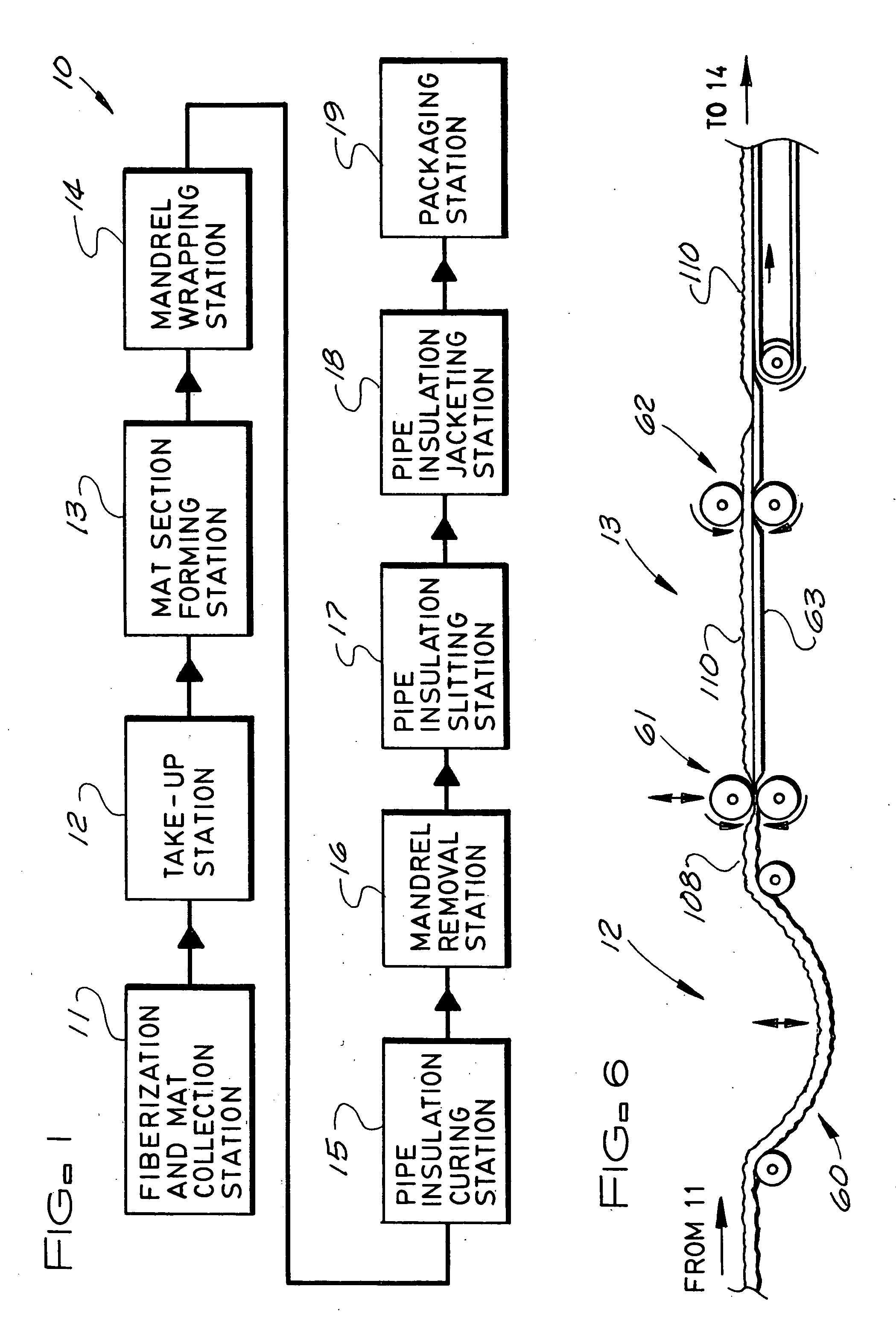
[0021]FIG. 1 schematically shows a jacketed pipe insulation production line 10 for making jacketed tubular pipe insulation assemblies by the process of the subject invention. The jacketed pipe insulation production line 10 includes a glass fiberizing and mat collection station 11, a mat take-up station 12, a mat section forming station 13, a mandrel wrapping station 14, a curing station 15, a mandrel removal station 16, a pipe insulation slitting station 17, a pipe insulation jacketing station 18, and a packaging station 19.

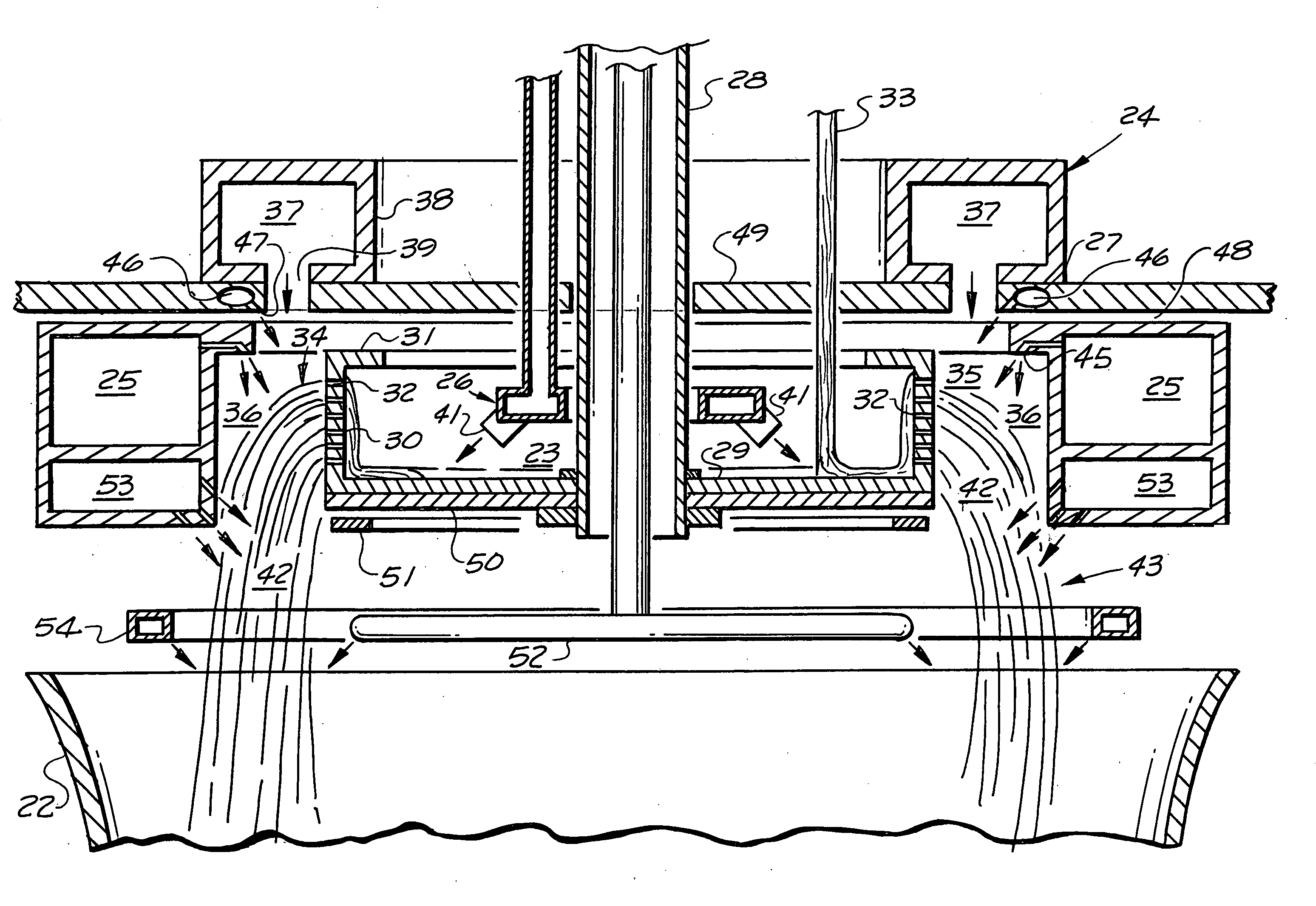
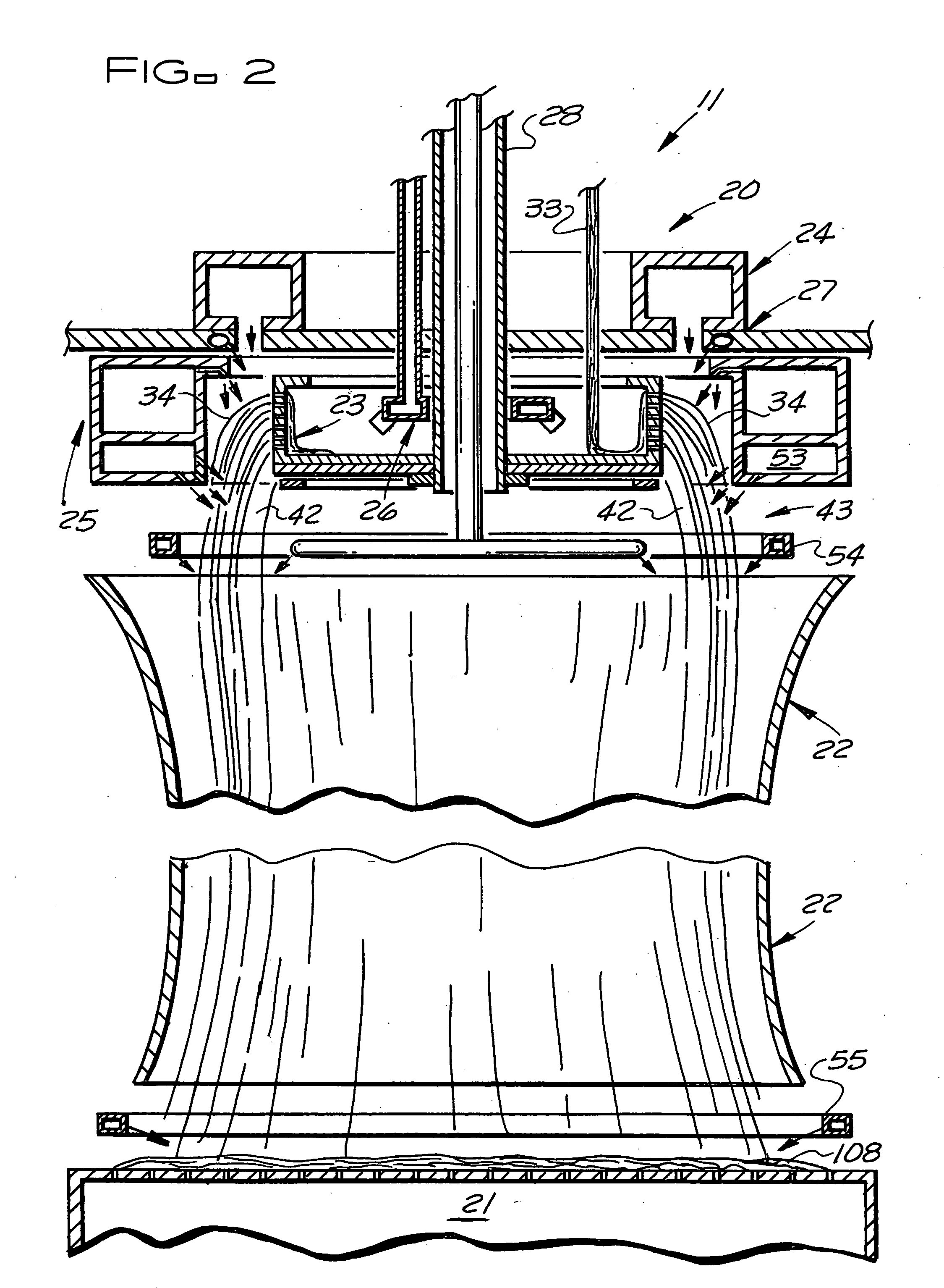
[0022] In a preferred embodiment of the glass fiberizing and mat collection station 11 shown in FIG. 2, the glass fiberizing and mat collection station includes a rotary fiberizing apparatus 20, a rotary perforated mat collection drum 21, and a forming tube 22 through which the fibers formed by the rotary fiberizing apparatus 20 pass to be collected on the rotary mat collection drum 21. The rotary fiberizing apparatus 20 includes a spinner disc 23, an external b...


PUM

PropertyMeasurementUnit
diameteraaaaaaaaaa
diameteraaaaaaaaaa
viscosityaaaaaaaaaa

Abstract

Tubular pipe insulation is made from a glass fiber mat produced utilizing a rotary glass fiberization process. A spinner disc is rotated to centrifuge molten glass through fiberization holes in an annular sidewall of the spinner disc and form primary glass fibers. The primary glass fibers are attenuated and formed into a veil where the fibers are dispersed to reduce in length the fiber networks formed from the fibers. Binder is applied to the fibers and the fibers are collected into a mat that, when pulled apart by longitudinally directed, opposing forces, separates across the width of the mat into two mat sections having feathered edges with substantially no fibrous stringers extending beyond the feathered edges for a distance greater than about four inches. The leading mat section is then wound about a mandrel and the binder in the mat is cured to form the pipe insulation.

Description

BACKGROUND OF THE INVENTION [0001] The subject invention relates to a process for making tubular glass fiber pipe insulation and more specifically, to an improved process for making tubular glass fiber pipe insulation that is made from a glass fiber mat produced utilizing a rotary glass fiberization process wherein the mat, when pulled apart by longitudinally directed, opposing forces, separates across the width of the mat into two mat sections having feathered edges with substantially no fibrous stringers extending beyond the feathered edges of the mat a distance greater than about four inches and typically no fibrous stringers extending beyond the feather edges of the mat a distance greater than about three inches. [0002] Tubular glass fiber pipe insulation is typically made from a glass fiber mat containing uncured binder by winding the glass fiber mat about a mandrel and curing the binder. The glass fiber mat is typically made utilizing a process known in the industry as a pot a...

Claims


Application Information

Patent Timeline
Patent Type & Authority Applications(United States)
IPC IPC(8): C03B37/10C03B37/04
CPCC03B37/04C03B37/045F16L59/028D04H3/07F16L59/026C03B37/06
Inventor BAKER, JOHN WAYNESMALLEY, RODNEY ROGERBORSA, ALESSANDRO G.FITZPATRICK, KENNETH CHARLES
Owner JOHNS MANVILLE CORP
Why Eureka
Try Eureka