Dielectric devices for a plasma arc torch

a plasma arc torch and dielectric device technology, which is applied in the direction of gas-filled discharge tubes, manufacturing tools, and solventing apparatus, can solve the problems of frequent nozzle replacement, increased operator visibility, and increased nozzle wear, so as to reduce the width of the torch head, the effect of reducing the double arcing event and increasing operator visibility

Active Publication Date: 2007-11-15
HYPERTHERM INC
View PDF23 Cites 44 Cited by
  • Summary
  • Abstract
  • Description
  • Claims
  • Application Information

AI Technical Summary

Benefits of technology

[0007]The subject matter of the invention generally relates to devices for protecting the nozzle in a plasma arc torch. In particular, the devices protect the nozzle by decreasing or eliminating double arcing events. In addition, the devices protect the nozzle by decreasing damaging interactions between the nozzle and the workpiece by increasing operator visibility. In one aspect, the invention relates to a dielectric shield for a plasma arc torch including a nozzle. At least a portion of the shield can include a non-ceramic substrate and a dielectric coating disposed on the non-ceramic substrate. The dielectric shield is sized to inhibit protrusion of the nozzle pass an end face of the dielectric shield.
[0008]Embodiments of this aspect of the invention can include one or more of the following features. The non-ceramic substrate can be a metal, such as, for example, copper, aluminum, steel, or an alloy. In certain embodiments, the non-ceramic substrate includes an electrically conductive material. In one embodiment, at least a portion of the dielectric shield includes a dielectric coating of an anodized material. The anodized material can be, for example, anodized aluminum or anodized copper. The dielectric coating can be formed of a ceramic layer, such as, for example a deposited layer of aluminum oxide. In some embodiments, the dielectric shield is made out of a composite material including a metallic inner substrate and an outer layer of ceramic. In another embodiment, the shield includes multiple coatings, which can be layered. The dielectric coating can be on an interior surface of the shield, on an exterior surface of the shield, over an entirety of the shield, and / or on an end face of the shield body. In another embodiment, the dielectric shield can have spring tangs for connecting or disconnecting the shield from the plasma arc torch. The shield can include multiple connecting portions, or multiple disconnecting portions, or both multiple connecting and disconnecting portions. The connecting and disconnecting portions allowing for portions of the dielectric shield to be replaced without having to replace the entire dielectric shield.
[0011]Another aspect of the invention relates to a torch head for a plasma arc torch for processing a metallic workpiece. The torch head includes a nozzle mounted relative to an electrode in the torch body, thereby defining a plasma chamber in which a plasma arc can be formed. The nozzle includes a conductive nozzle body portion and defines a nozzle exit orifice extending therethrough. The shield of the torch head includes a non-ceramic portion, a dielectric portion, and an end face portion. The dielectric shield portion can inhibit the nozzle body portion from extending pass the end face and preventing arcing within the torch head when the shield is secured within an arcing distance of the nozzle.
[0017]There are numerous advantages to the aspects of the invention described above. For example, the dielectrically coated shields and / or nozzles described above electrically insulate the nozzles from the workpieces. As a result, double arcing events are reduced and in some embodiments eliminated. In addition, the width of the torch head (i.e., the overall width of the combined electrode, nozzle, and shield) is reduced, thereby increasing operator visibility. Another advantage of using a dielectric device that includes a non-ceramic substrate and a dielectric coating is increased impact and thermal resistance. In conventional torches with non-conducting, ceramic shields, damage to the ceramic shields occurs often due to its brittle nature and inability to withstand thermal abuse. In the present invention, the dielectric devices provide comparable electrical isolation as ceramic shields, however, the dielectric devices in accordance with the invention can withstand greater impacts and thermal stresses due to the underlying non-ceramic substrate. In certain embodiments, convenience and efficiency are increased by include spring tangs and / or connecting and disconnecting portions of the shield. That is, a shield with spring tangs and / or connecting and disconnecting portions can be quickly and easily attached and removed from a torch body, thereby saving operational costs. In addition, shields including connecting and disconnecting portions can be piecemeal replaced. That is, as a portion of the shield wears away or becomes covered in slag, that portion can be removed and replaced without sacrificing the entire shield.

Problems solved by technology

Many of the torch components are consumable in that they deteriorate over time and require replacement.
Frequently during torch operation, the operator is constrained by space or visibility, which may lead to inadvertent contact of the side of the nozzle to the workpiece resulting in “double arcing.” Double arcing is a condition where the plasma arc deviates from its intended electrode to workpiece path and instead goes from the electrode to the nozzle and then to the workpiece—causing electrical continuity between the nozzle and the workpiece.
Double arcing causes premature wear to the nozzle and results in frequent nozzle replacement and additional expense.
In addition, double arcing can cause nozzle stickiness, which inhibits accurate hand control of the torch.
The use of a shield, which is electrically floating, around the nozzle helps to eliminate the risk of double arcing, but currently available shields have undesirable limitations.
Despite nozzle shields being pervasive in the commercial market, they are often bulky and inhibit visibility of the plasma arc by the operator.
One design difficulty for conductive shields is establishing a sufficient dielectric gap.
In conventional torches, the conductive shield is positioned at least an arcing distance away from the nozzle causing the total covered volume surrounding the plasma arc to be large, thereby reducing operator visibility.
A ceramic shield can be used in place of a conductive shield, but problems associated with these consumables exist.
One difficulty with ceramic shields in plasma arc torch systems, despite their ability to solve the spacing and electrical isolation problems, is that they cannot withstand the thermal and impact shocks that occur during normal industrial use.
In addition, ceramic shields are generally bulky and therefore decrease operator visibility.
Moreover, ceramic shields are often too brittle for most hand torch systems.

Method used


Image

  • Dielectric devices for a plasma arc torch
  • Dielectric devices for a plasma arc torch
  • Dielectric devices for a plasma arc torch

Examples


Embodiment Construction

[0029]The present invention features a device for a plasma arc torch that minimizes the possibility of double arcing and maximizes cutting accuracy by improving operator visibility and edge starting (i.e., minimizing nozzle stickiness).

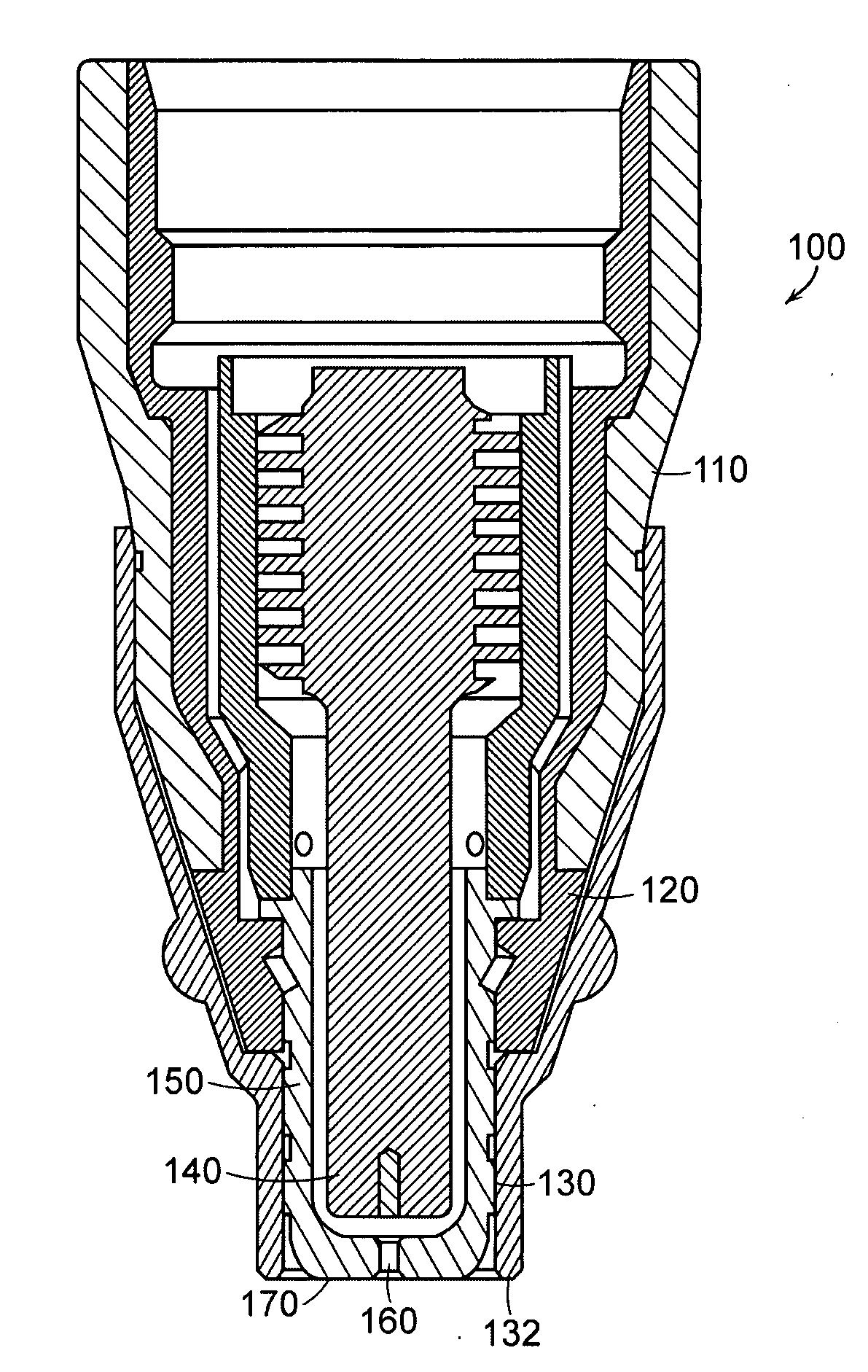
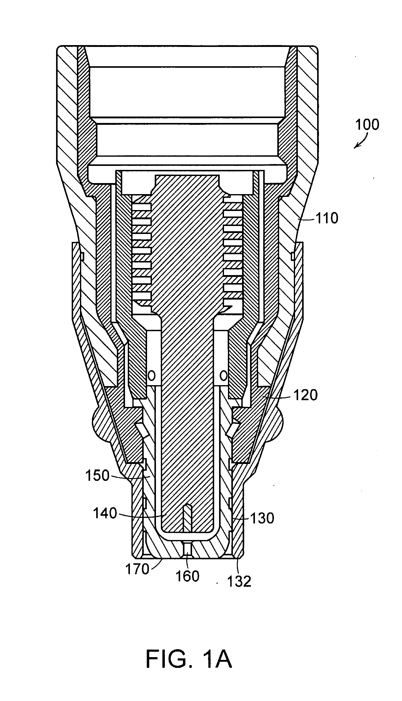
[0030]FIG. 1A shows a vertical cross sectional view of one embodiment of a plasma arc torch 100. The torch includes an electrode 140, a nozzle 150 with a central exit orifice 160, a retaining cap including an inner portion 120 and an outer portion 110, and a dielectric shield 130. The dielectric shield 130 can be positioned to contact the nozzle 150 without the threat of double arcing, due to the non-conductive nature of dielectric materials. That is, the dielectric shield 130 electrically insulates the conductive nozzle 150. The dielectric shield 130 extends at least to the end face of the nozzle 170 and is sized so that the nozzle 150 does not protrude pass an end face 132 of the shield 130. The plasma arc torch 100 produces a plasma arc, which is a...


PUM

PropertyMeasurementUnit
dielectricaaaaaaaaaa
electrically conductiveaaaaaaaaaa
dielectric shieldaaaaaaaaaa

Abstract

Apparatus and methods for thermally processing a workpiece include directing a plasma arc to the workpiece and using a dielectric shield or dielectric coating to protect a forward portion (e.g., a torch head) of a plasma arc torch. The dielectric shield or dielectric coating covers a nozzle disposed within the torch head and protects the nozzle from the effects of slag and double arcing. The shield also improves operator visibility due to the spatial relationship between the dielectric shield and the nozzle.

Description

RELATED APPLICATIONS[0001]This application is a continuation-in-part of U.S. Ser. No. 11 / 432,282 entitled “Generating Discrete Gas Jets in Plasma Arc Torch Applications,” filed on May 11, 2006. This application claims the benefit of U.S. Provisional Application Ser. No. 60 / 825,477, entitled “Dielectric Shield for a Plasma Arc Torch,” filed on Sep. 13, 2006. The entire disclosures of U.S. Ser. No. 60 / 825,477 and U.S. Ser. No. 11 / 432,282 are incorporated herein by reference.TECHNICAL FIELD[0002]The invention relates to use of a dielectric device with a plasma arc torch. Specifically, the invention relates to a dielectric device positioned relative to, or on a nozzle such that operator visibility of the plasma arc is increased and the risk of double arcing is decreased.BACKGROUND[0003]Plasma arc torches are widely used in the cutting, welding and heat treating of metallic materials. A plasma arc torch generally includes a cathode block with an electrode mounted therein, a nozzle with a...

Claims


Application Information

Patent Timeline
Patent Type & Authority Applications(United States)
IPC IPC(8): B23K10/02
CPCH05H1/34H05H2001/3473H05H2001/3457H05H1/3473H05H1/3457
Inventor ROBERTS, JESSE A.KORNPROBST, MICHAEL F.COOK, DAVID JONATHAN
Owner HYPERTHERM INC
Why Eureka
Try Eureka