Multi-Dimensional Broadband Track and Trace Sensor Radio Frequency Identification Device

a radio frequency identification and multi-dimensional technology, applied in the direction of instruments, computing, and feed intermediates, can solve the problems of multiple rfid tag devices modulating within the same area and within limiting the effectiveness of rfid tags having 2d antennas, and affecting signal interference of multiple rfid tag devices modulating within the same area and the same frequency bandwidth, so as to reduce the size of the overall tag device, reduce the loss of efficiency, and directivity optimum read angle angl

Inactive Publication Date: 2007-11-15
EVELAND RONALD
View PDF70 Cites 17 Cited by
  • Summary
  • Abstract
  • Description
  • Claims
  • Application Information

AI Technical Summary

Benefits of technology

[0009] According to a first aspect of the present invention, an antenna constructed according to the present invention for use with an RFID tag device is formed with a three dimensional (3D) structure. The 3D structure of the antenna enables the antenna to be constructed to have a size smaller than that of conventional two-dimensional antennas, consequently reducing the size of the overall tag device, but without any loss of efficiency of the 3D antenna compared to 2D antennas. Further, depending upon the particular shape of the 3D antenna, the directivity and optimum read angle of the antenna are increased significantly.

Problems solved by technology

However, with these types of antennas, there are certain inefficiencies associated with their design that limits the effectiveness of the RFID tags having 2D antennas.
Most often, this requires that the RFID tag device be approximately four (4) inches square, rendering the tag device unworkable for many applications in which the item or section of the item to which the RFID tag device would be attached too small for use with RFID tag devices of this size.
Furthermore, based on the relatively large size of the bandwidth sections that the antennas are designed to operate in, multiple RFID tag devices modulating within the same area and within the same frequency bandwidth are often affected by signal interference.
The reason for this is that the licensed and unlicensed frequencies in which RFID tag devices are designed for use have a limited amount of bandwidth.
Because the 2D antennas can only be accurately formed or tuned below a limited bandwidth section, a correspondingly limited number of physical channels or sections are available within that bandwidth.
Thus, when multiple RFID tag devices are being utilized in a given location, many of these tags will be operating within the same bandwidth section, and those devices operating on the same frequencies can cause signal interference, thereby affecting the signal quality of transmitted read data.
Also, multiple overlapping channels, such as those sections to which RFID tag devices are tuned in a given bandwidth, can generate random, unnecessary signal interference.
Therefore, for optimum RFID tag device operation, only a limited amount of RFID tag devices can be within the same area or read range, greatly reducing the utility of these prior art RFID tag devices.
However, due to power constraints that are placed on the signals that can be utilized in a given frequency band, and specifically those which are available for use with RFID tag devices, oftentimes the maximum power for the signal to be received by the antenna for the RFID tag device is not sufficient to completely eliminate all interference from other RFID tag devices.
In addition, the 2D linearly polarized antennas used in current RFID tag designs reduce the optimum read angle of the device, further reducing the optimum power transfer from RFID tag device to RFID reader.

Method used


Image

  • Multi-Dimensional Broadband Track and Trace Sensor Radio Frequency Identification Device
  • Multi-Dimensional Broadband Track and Trace Sensor Radio Frequency Identification Device
  • Multi-Dimensional Broadband Track and Trace Sensor Radio Frequency Identification Device

Examples


second embodiment

[0054] Referring now to FIG. 13, in the present invention, the antenna 110 is formed of a pair of conductive material strips 118, which can be formed of a metal or a metal oxide, for example, though other materials can also be utilized, each having a spiral shape, and preferably an Archimedean spiral shape, that extend outwardly in a gradually increasing, radially expanding manner that is positioned on a suitable substrate material 120, e.g., silicon, that is less than 3 mm2 in size, and preferably less than 2.5 mm2 in size. The pair of spiral strips 118 are disposed in the same plane on the surface of the substrate material 120, and have a turn ratio of 0.255, and are approximately 2.80 turns in length. The innermost ends 122 of each spiral 118 are joined to one another on the substrate 120 by a suitable receiver device 126, which is can be a data chip. The size of the spiral strips 118, i.e., the turn ratio and turn length, varies for each antenna 110, similarly to the previous em...

third embodiment

[0055] In a third embodiment the present invention, best shown in FIG. 15, the tag 212 can be formed with a pair of spiral antennas 218 on between 3 mm2, and preferably less than 2.5 mm2 of a substrate material 220 formed from a suitable material, such as silicon. The pair of spiral strips 218 are disposed in different planes on opposed surfaces of the substrate material 220, and have a turn ratio of 0.255, and are approximately 2.88 turns in length. The innermost ends 222 of each spiral 218 forming the antenna 210 are connected to one another by a receiver device 226 that can include a suitable structure 230 that extends through the substrate material 220 between the innermost ends 222 of the spirals 218. In this construction, the two spirals 218 can function as a single antenna 210, or can be configured to operate as separate antennas 210, if desired. The length of the structure 230 is selected as desired depending upon the size of the substrate material 220 and the size of the sp...

first embodiment

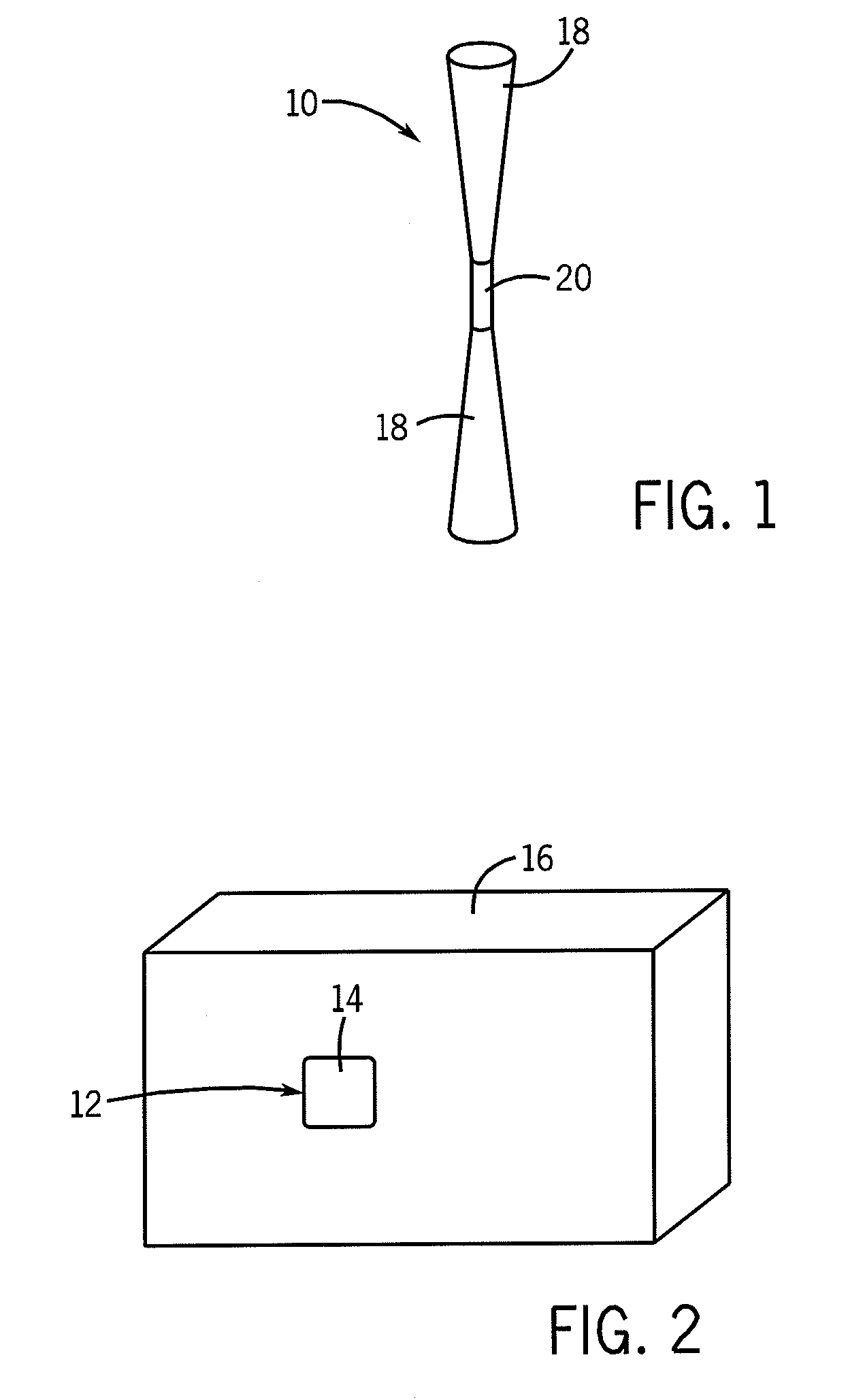
[0059] In short, as illustrated by these results, the radiation efficiency of each 3D antenna 110 and 210 is maintained one hundred percent, and the return loss is minimal, such that the reduction in size from the 3D antenna configuration does not negatively affect the ability of the antennas 110 and 210 to function in a manner similar to the conventional antennas currently in use with RFID tag devices, similarly to the bi-conical antennas 10 in the

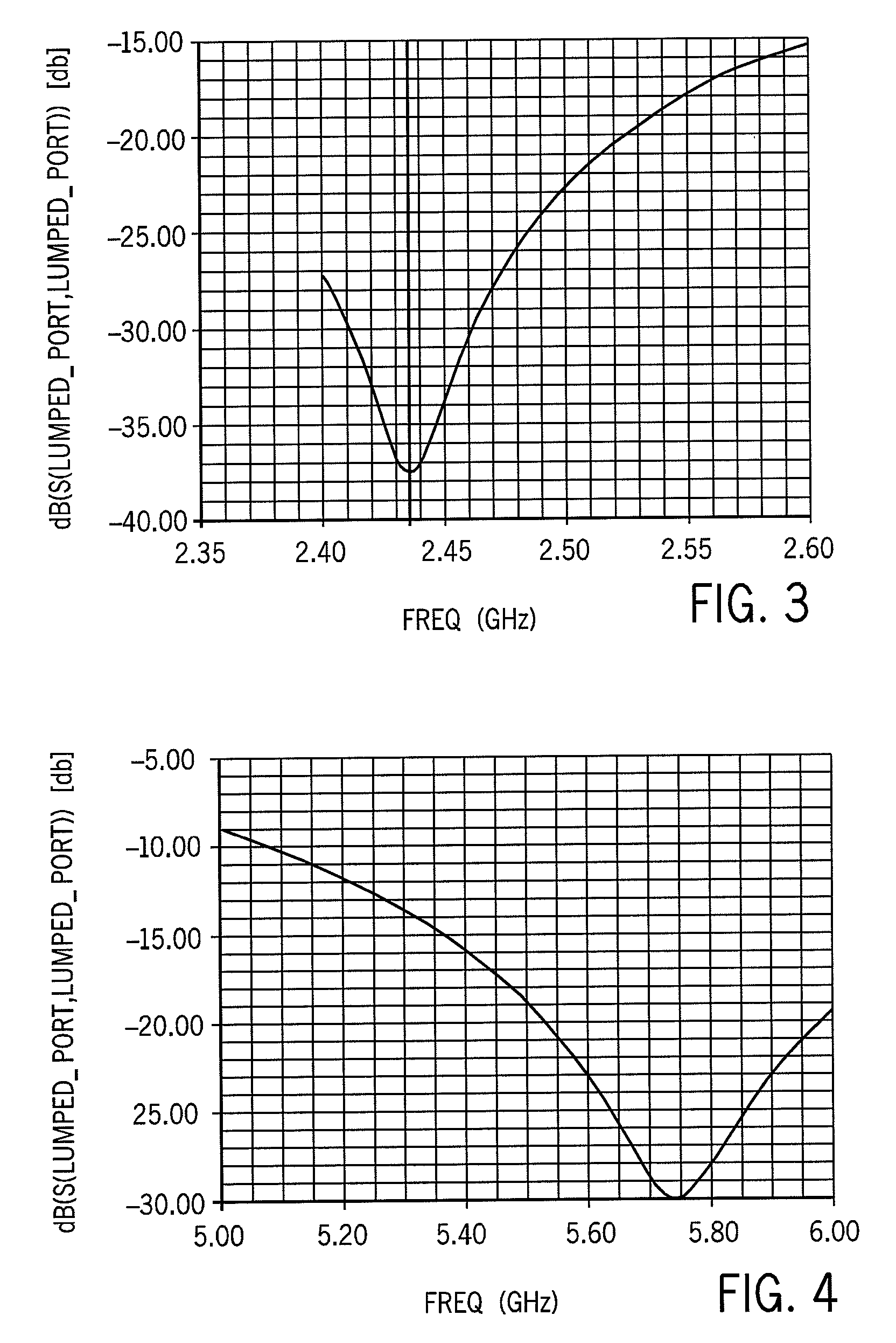
[0060] In employing the antennas 110 or 210 for use in RFID tag devices 12, in a preferred implementation similar to the first embodiment, the RFID tag device 12 includes a signal filter component 132 or 232 as shown in FIGS. 17 and 18 that are formed of an RLC network to achieve circuit resonance near a particular frequency for antennas 110 and 210. The filters 132 and 232 narrow the effective frequency or the antennas 10 and 210, such that the responses for the antennas 110 and 210 are as illustrated in FIGS. 19 and 20. The antennas 110...


PUM


Abstract

A broadband antenna constructed according to the present invention for use with an RFID tag device is formed with a three dimensional (3D) structure. The 3D structure of the antenna enables the antenna to be constructed with a size smaller than that of conventional two-dimensional antennas, consequently reducing the size of the overall tag device, but without any loss of efficiency. The 3D antennas are formed with Archimedean spiral sections and can be tuned to a specific frequency in a particular frequency band, enabling many more unique RFID devices to be defined and operate within that band in conjunction with a reader utilizing a frequency-hopping method without interfering with one another. Additionally, the antenna can receive signals from a higher frequency band than the band in which the antenna resonates to enable those higher power signals to supply power to the device without interfering with the resonant frequency signals received by and transmitted from the RFID device.

Description

CROSS-REFERENCE TO RELATED APPLICATIONS [0001] This application claims priority under 35 U.S.C. § 120 as a continuation-in-part from U.S. patent application Ser. No. 11 / 599,492, filed on Nov. 14, 2006, which claims priority under 35 U.S.C. § 119 from U.S. Provisional Patent Application Ser. No. 60 / 736,566, filed on Nov. 14, 2005, and incorporated by reference in its entirety herein.FIELD OF THE INVENTION [0002] The present invention relates, in general, to passive radio frequency identification (RFID) data tag devices, and more particularly to tags of this type that are formed with a three-dimensional antenna. BACKGROUND OF THE INVENTION [0003] Current RFID tag designs use two-dimensional (2D) linearly polarized antennas to transmit and receive data from the tag. These antennas can be formed in any suitable manner, such as by being placed or wound onto the tag when formed of a wire coil, or by being printed directly on a substrate for the tag when formed of a conductive ink or metal...

Claims


Application Information

Patent Timeline
Patent Type & Authority Applications(United States)
IPC IPC(8): G08B13/14
CPCH01Q9/28G06K19/07749
Inventor EVELAND, RONALD
Owner EVELAND RONALD
Why Eureka
Try Eureka