Methods And Systems For Removing Copper From Ferrous Scrap

Inactive Publication Date: 2007-11-15
UNIV OF UTAH RES FOUND
11 Cites 4 Cited by

AI-Extracted Technical Summary

Problems solved by technology
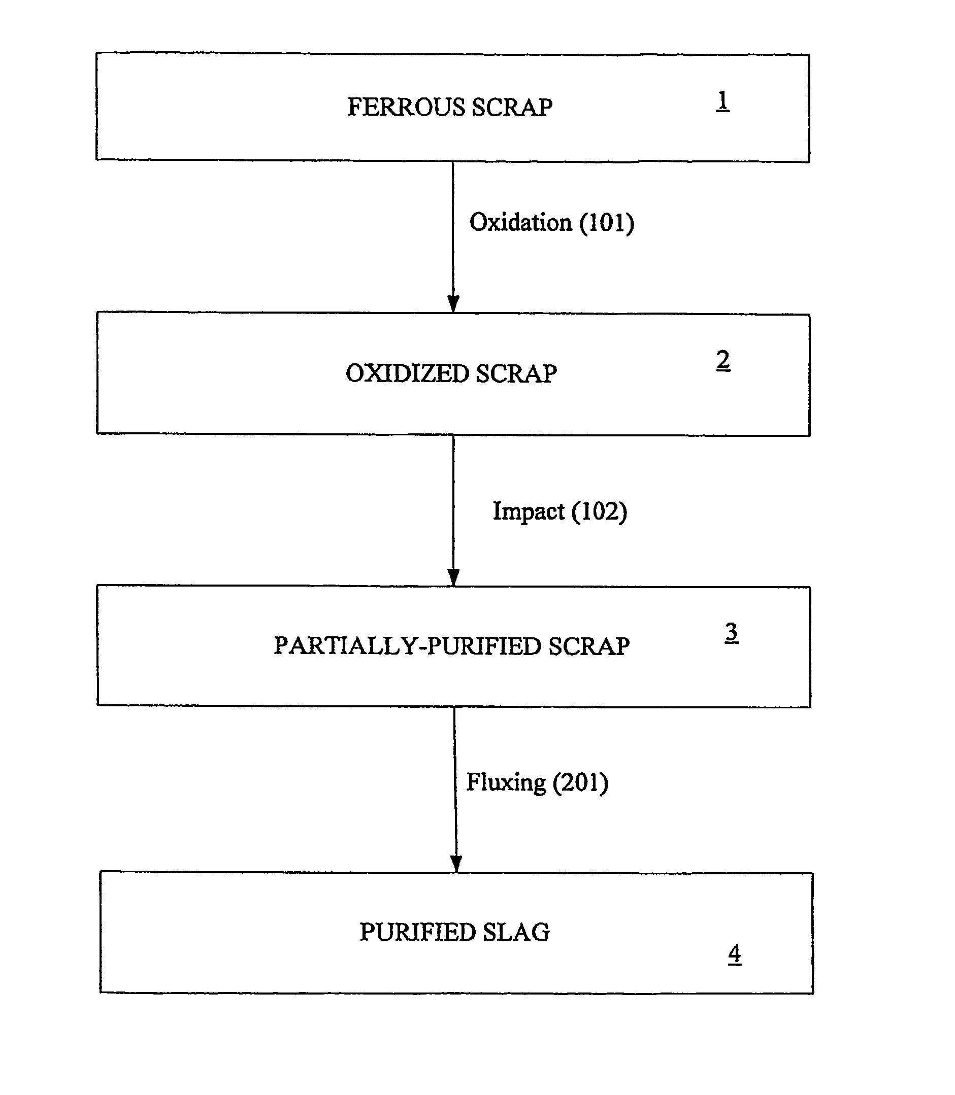
Unfortunately, much of the available iron and steel scrap, in particular those produced in automobile manufacturing, is contaminated with residual impurity elements such as copper and tin.
Such impurities prevent the use of steel scrap directly for such higher-quality steel products.
Of those impurities, copper (Cu) is typically cited as the most harmful because it can limit the end uses of the steel scrap.
For example, excessive copper levels can cause problems in process that use the steel scrap, e.g., severe surface cracking during hot rolling (hot shortness), inhibit recrystallization during hot forming, and reduce ductility in deep drawing.
It is estimated that quality of steel scrap will deteriorate marke...

Method used

[0026] The temperature of about 500° C. was used to minimize or prevent the formation of wustite (FeO) on the steel. Once the wustite starts to form, the oxidation rate of steel increases since the wustite is cation-deficient, defeating the purpose of oxidation process 101 to minimize the oxidation of steel in the ferrous scrap.
[0032] Most ferrous scrap, such as that obtained from a scrap yard, is already rusted and therefore covered with a thin iron oxide film. Thus, the loss of iron by the oxidation of scrap is expected to be minimal. On the other hand, copper will be continuously oxidized...

Benefits of technology

[0008] The invention provides methods and systems for removing copper from ferrous scrap. Some amounts of copper in ferrous scrap are removed by oxidation and subsequent mechanical impact of the oxidized scrap. Further removal of copper from the solid scrap can be achieve...

Abstract

Methods and systems for removing copper from ferrous scrap are described. Some amounts of copper in ferrous scrap are removed by oxidation and subsequent mechanical impact of the oxidized scrap. Further removal of copper from the solid scrap can be achieved by fluxing the copper oxide below the melting point of ferrous scrap using CaO—SiO2—B2O3- and Na2O—SiO2—B2O3-based slags. Using the invention, copper can be removed from ferrous scrap in a natural, cost-effective, and environmental-friendly manner.

Application Domain

Basic electric elementsProcess efficiency improvement +2

Technology Topic

SlagScrap +4

Image

  • Methods And Systems For Removing Copper From Ferrous Scrap
  • Methods And Systems For Removing Copper From Ferrous Scrap
  • Methods And Systems For Removing Copper From Ferrous Scrap

Examples

  • Experimental program(1)

Example

EXAMPLE
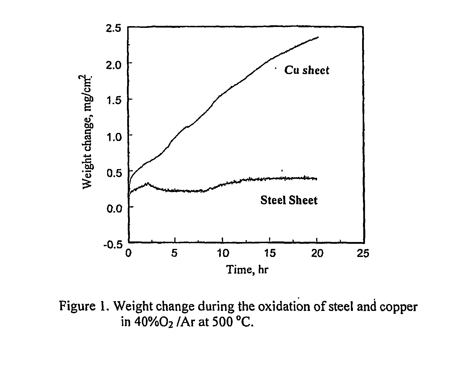
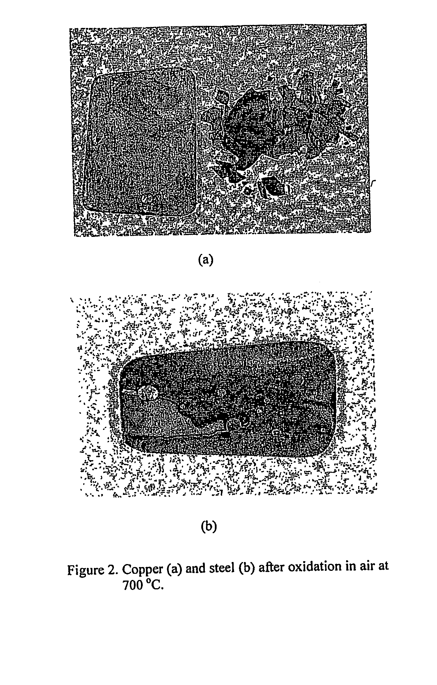
[0048] Coupon specimens for copper and steel were prepared for the oxidation experiments. A big piece of steel was obtained from the body of a car in a junk yard and the piece was cut to create smaller specimens for the oxidation tests. The coupon specimens were abraded and polished, and then degreased and cleaned in an ultrasonic cleaner. The experimental apparatus used for the oxidation tests were described in Gilsoo Han and W. D. Cho, “High-Temperature Corrosion of Fe3Al in 1% Cl2/Ar,”Oxidation of Metals, Vol. 58, 2002, p. 391, and contained a computer-controlled microbalance, a kanthal-wound furnace, gas train and mixing chambers of reagent gases.
[0049] The specimen was loaded with Pt-wire (0.02 inch diameter) inside a fused quartz reaction tube. The purified argon gas flow was maintained until the desired temperature was obtained. After the temperature of furnace reached the reaction temperature and was stable under the argon atmosphere, a O2—Ar gas mixture was introduced into the reaction tube at a flow rate of 100 ml/min, superficial flow rate of 1 cm/s. From this point, the weight change of the specimen was measured using an electrobalance (D101 Cahn Balance) which had a 1 μg sensitivity. After the predetermined reaction time, the specimens were cooled in the furnace and removed in order to examine the oxidized specimen. The characterization of corrosion products was made by XRD (X-ray Diffraction), SEM (Scanning Electron Microscopy) and EDS (Energy Dispersive Spectrometer).
[0050] For the dissolution of copper oxide in molten slag, copper wire wound on a steel rod was oxidized completely in air and subsequently the steel rod was immersed in static molten slag. The resistance-heated furnace that can attain up to 1700° C. was heated by platinum-rhodium alloy windings and the temperature of the furnace was controlled by a B-type thermocouple as described in W. D. Cho and Peng Fan, “Diffusional Dissolution of Alumina in Various Steelmaking Slags,”ISIJ International, Vol. 44, pp. 229-234, 2004.
[0051] A powder mixture of the slag components was then charged in an alumina crucible which was placed into an alumina tube. After melting the powders completely, the steel rod wound with oxidized copper wire was immersed in the molten slag and withdrawn after a predetermined time period.
[0052] In addition to any previously indicated variation, numerous other modifications and alternative arrangements may be devised by those skilled in the art without departing from the spirit and scope of the invention and appended claims are intended to cover such modifications and arrangements. Thus, while the invention has been described above with particularity and detail in connection with what is presently deemed to be the most practical and preferred aspects of the invention, it will be apparent to those of ordinary skill in the art that numerous modifications, including but not limited to, form, function, manner of operation and use may be made without departing from the principles and concepts set forth herein.

PUM

PropertyMeasurementUnit
Temperature400.0 ~ 700.0°C
Temperature400.0 ~ 900.0°C
Time14400.0 ~ 21600.0s

Description & Claims & Application Information

We can also present the details of the Description, Claims and Application information to help users get a comprehensive understanding of the technical details of the patent, such as background art, summary of invention, brief description of drawings, description of embodiments, and other original content. On the other hand, users can also determine the specific scope of protection of the technology through the list of claims; as well as understand the changes in the life cycle of the technology with the presentation of the patent timeline. Login to view more.
Why Eureka
Try Eureka