Eureka AIR delivers breakthrough ideas for toughest innovation challenges, trusted by R&D personnel around the world.

Information technology process for prefabricated building panel assembly

a technology of information technology and prefabricated panels, applied in the direction of manufacturing tools, instruments, other domestic objects, etc., can solve the problems of time and expense required to construct a structure, many problems in conventional building construction, and subject to a variety of inefficiencies

Inactive Publication Date: 2007-11-15
GENESISTP INC
View PDF99 Cites 21 Cited by
  • Summary
  • Abstract
  • Description
  • Claims
  • Application Information

AI Technical Summary

Benefits of technology

[0006] One attribute of certain embodiments is that they use cold-formed steel raw materials instead of traditional wood and concrete construction methods. There are several advantages to the structures that result from the disclosed technology both to the builders and to the consumers that live or work in these structures. The advantages to the builders are stronger buildings that can withstand hurricane conditions and significant seismic forces, increased speed of construction, improved quality of construction which reduce after sales service costs, safer construction due to the use of non-combustible materials, and less on-site labor to construct these projects. The benefits to the consumers that live in these homes or work in these buildings are better energy performance, environmental benefits due to use of recycled steel, homes that last longer, and better indoor air quality, to name just a few.
[0036] In one embodiment, each lifting member may be configured to engage the edge of the panel from below. As a result, the panel is only supported from below, with a minimal force applied to the edges of the panel. This may limit any damage to the panel during transport. A small force may be applied to the edges of the panel by the support arms to assist in stabilizing the panel.
[0039] In one embodiment, the method can further include the step of generating, in response to the structural specifications, a parts list for the prefabricated panels. The method can also further include the steps of manufacturing the prefabricated panels in accordance with the structural specifications and collecting the prefabricated panels and other parts for delivery. The collecting step can include organizing the panels in a specific order in accordance with the structural specifications to facilitate the ease and speed of assembly upon delivery to a construction site.
[0047] Another aspect of the invention can include a kit for manufacturing a habitable enclosure using prefabricated panels. The kit can include a plurality of prefabricated metal panels, at least one stabilizing element to releasably hold the plurality of prefabricated panels in a predetermined manner during transportation, and assembly instructions for assembly of the plurality of panels into the habitable enclosure, wherein the plurality of prefabricated metal panels are organized in accordance with the assembly instructions during transportation in order to facilitate ease and speed of construction.
[0049] In one embodiment, the plurality of prefabricated metal panels may be organized according to the order of use of the panels during construction. The plurality of prefabricated metal panels may be assembled into a plurality of bundles for transportation. This allows the kit to be transported on a number of transport vehicles, and / or be transported in stages. The plurality of bundles can each include a stabilizing element. The kit can further include at least one protective element. The protective element may be configured to protect the plurality of prefabricated metal panels from damage during transportation.

Problems solved by technology

Conventional building construction has many problems, not the least of which is the time and expense required to construct a structure, such as a multi-story home or office building.
Much construction work is custom work that is performed on-site, and so is subject to a variety of inefficiencies.
The construction and organization of these panels may, however, be complicated in itself.
As a result, many of the expected advantages of the use of prefabricated panels in building construction have not been fully realized, especially with respect to the systematic management and control of construction of a building from initial design stage to final assembly.

Method used


Image

  • Information technology process for prefabricated building panel assembly
  • Information technology process for prefabricated building panel assembly
  • Information technology process for prefabricated building panel assembly

Examples


Embodiment Construction

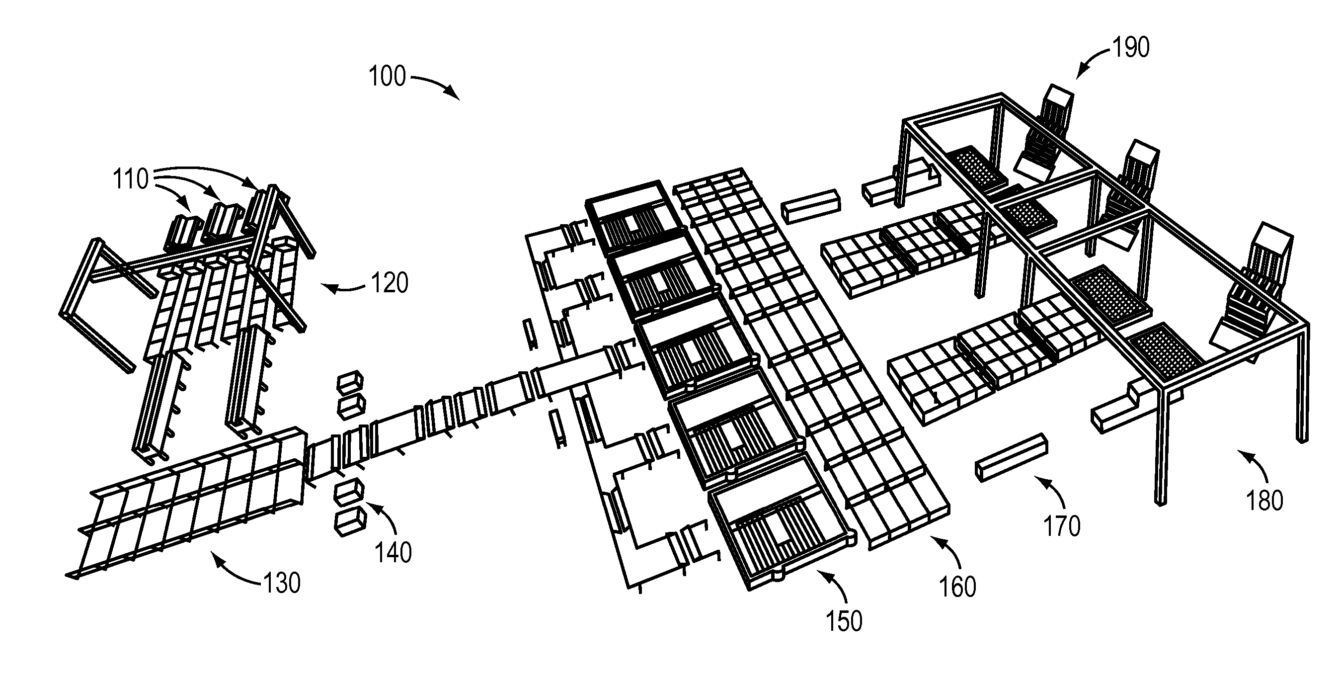
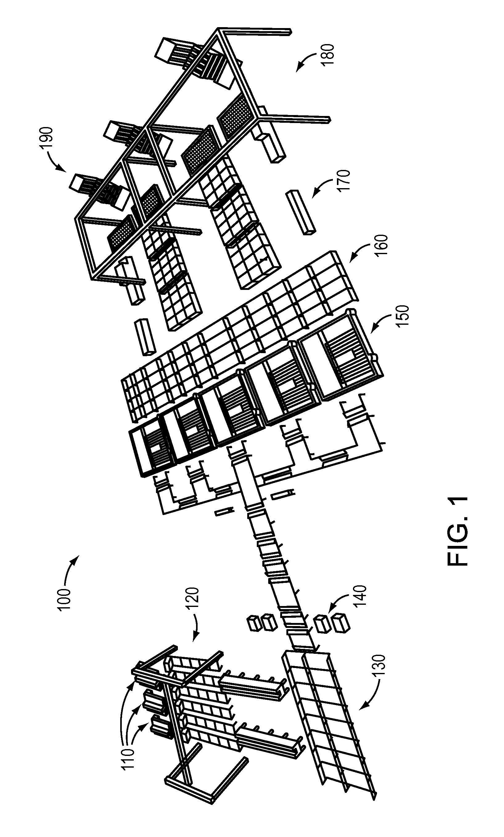
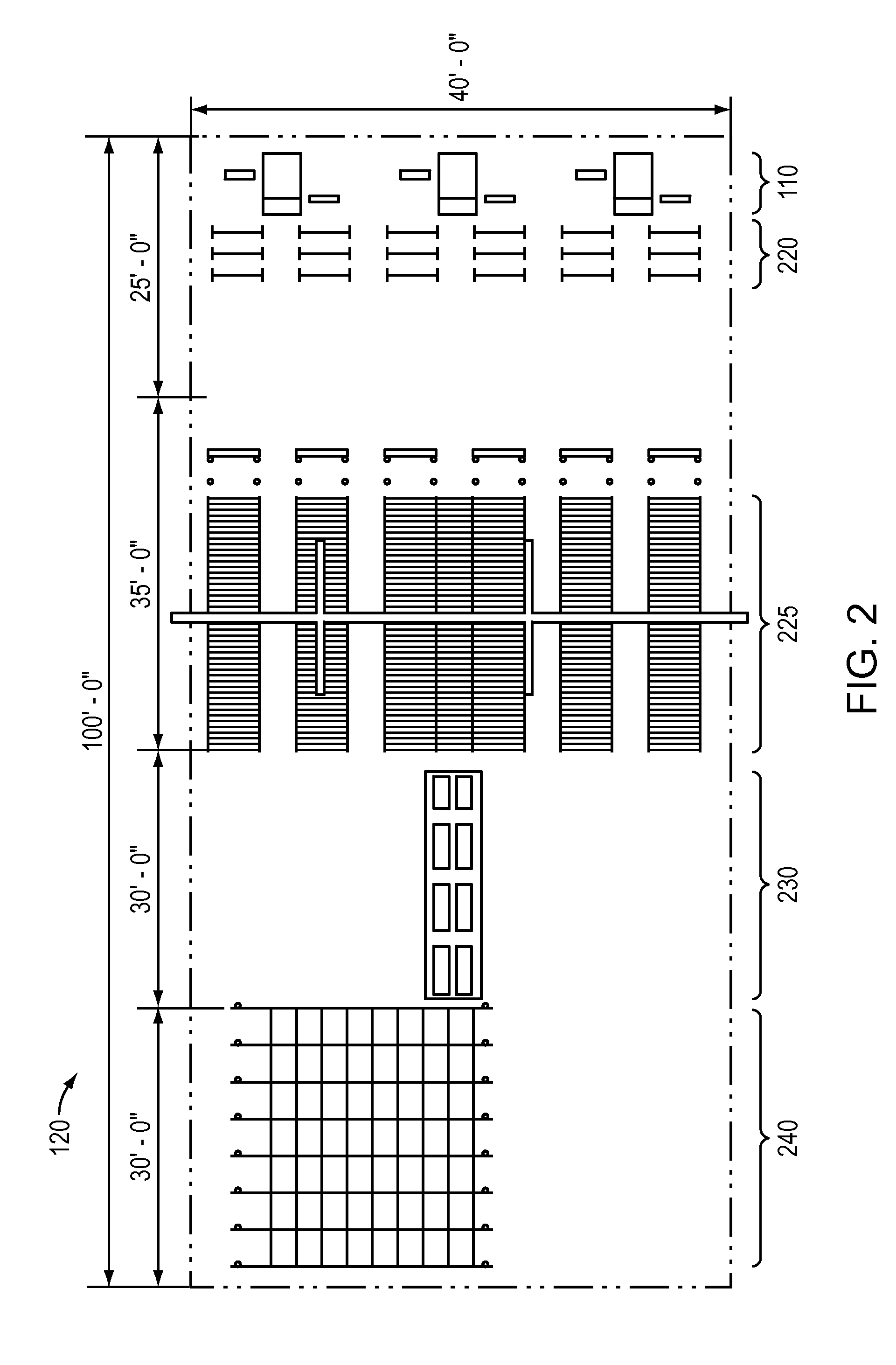
[0093] One embodiment of the invention can include a material transport system for use in manufacturing panels for building construction, such as in buildings constructed from steel frame or other appropriate building materials, including, but not limited to, aluminum or other metals, wood, plastics, composite materials, or combinations thereof. The material transport system can include a rail system allowing an empty tray to be loaded with appropriate materials for a specific panel. These trays can then be used to transport the panel materials to different stations on a manufacturing production line. Stations on the production line can include, but are not limited to, pre-welding, construction (at “framing tables”), post-welding, and sheeting stations. The panels can be moved between one or more of the stations on roller systems. The trays for carrying the original materials can be returned to the starting location, either automatically or manually, after delivery of the materials ...


PUM


Abstract

The disclosed technology enables manufacturers to efficiently design and manufacture structural wall panels, floor panels and roof panels from cold-formed steel for use in residential and commercial construction. The panels are individual components that can be installed at a building site to form a structure that includes walls, floor and a roof. Structures may be manufactured in a manufacturing facility and delivered to a construction site for installation.

Description

CROSS-REFERENCE TO RELATED APPLICATIONS [0001] This application claims priority to and the benefit of U.S. provisional patent application Ser. No. 60 / 791,982 filed Apr. 14, 2006, the disclosure of which is being incorporated herein by reference in its entirety. This application is related to U.S. patent application Docket No. GTP-001, U.S. application Ser. No. 11 / 707,650, entitled “Material Transport System for Building Panel Assembly,” U.S. patent application Docket No. GTP-002, U.S. application Ser. No. 11 / 707,638, entitled “Framing Table for Building Panel Assembly,” U.S. patent application Docket No. GTP-003, U.S. application Ser. No. 11 / 707,563, entitled “Bi-Directional Roller Table,” U.S. patent application Docket No. GTP-004, U.S. application Ser. No. 11 / 707,649, entitled “Automatic Pinning Process for Building Panel Assembly,” U.S. patent application Docket No. GTP-005, U.S. application Ser. No. 11 / 707,555, entitled “Overhead Gantry for use in Building Panel Construction,” U...

Claims


Application Information

Patent Timeline
Patent Type & Authority Applications(United States)
IPC IPC(8): G06F19/00E04C2/00
CPCB21F27/128B23P21/004B23P19/04
Inventor MIFSUD, VINCENT D.APRILE, GIUSEPPE CORRADOCHURCHILL, MICHAEL J.TRANCREDI, MICHELE
Owner GENESISTP INC
Why Eureka
Eureka Blog
Learn More