Hydrogen production using plasma- based reformation
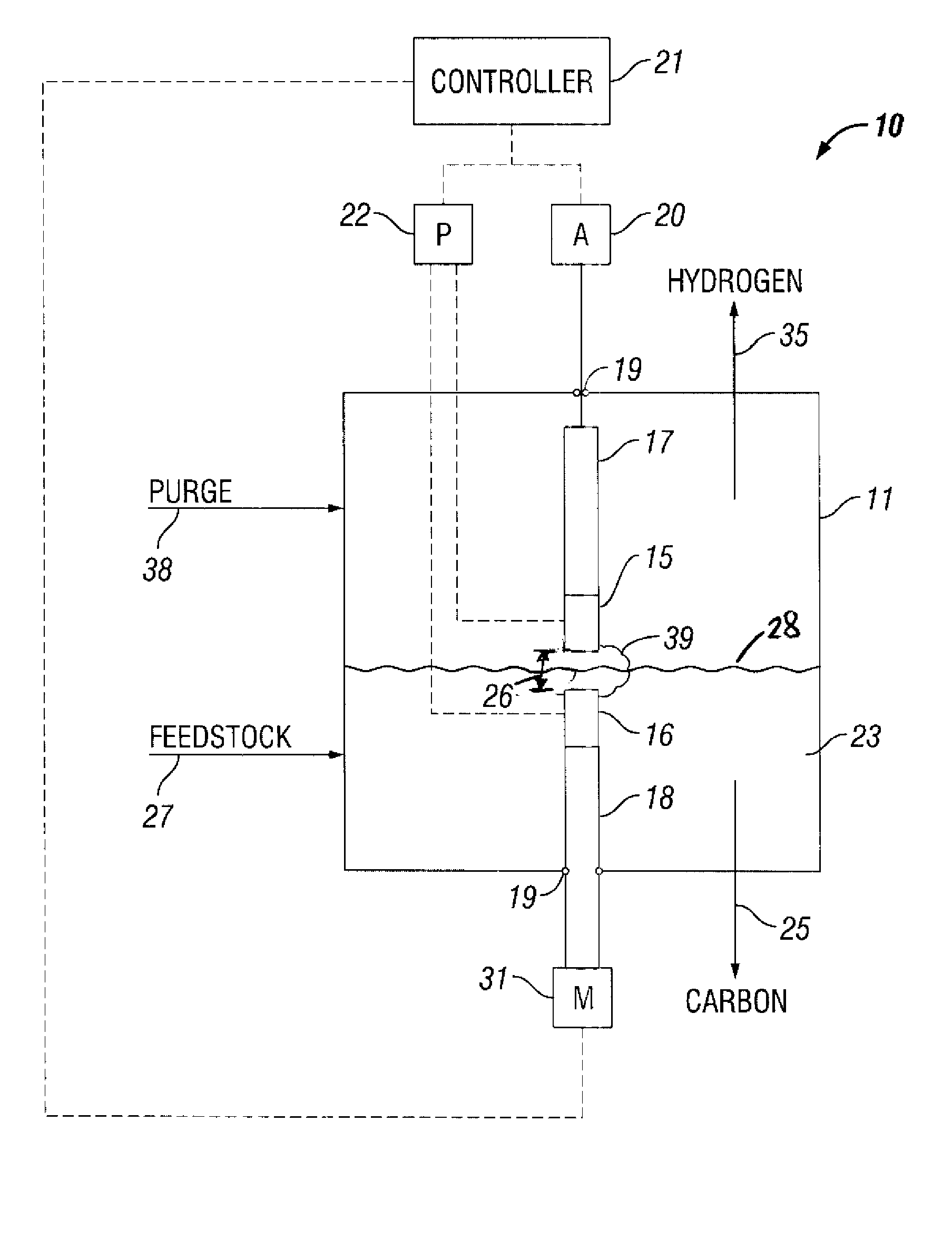
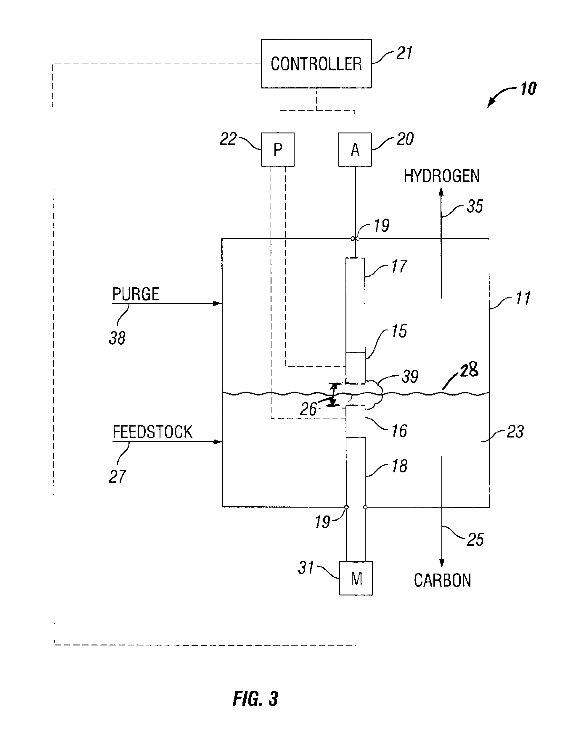
a plasma-based, plasma technology, applied in the field of plasma systems, can solve the problems of reducing the plasma size, and achieve the effects of increasing the hydrogen gas production rate, reducing the gap length, and increasing the voltage potential
- Summary
- Abstract
- Description
- Claims
- Application Information
AI Technical Summary
Benefits of technology
Problems solved by technology
Method used
Image
Examples
example 1
Horizontal Electrode Configuration
[0072]FIG. 4 is a perspective top view of a plasma reformer operated in accordance with the present invention. The plasma reformer 40 includes a reactor chamber 11 made from a 2″ diameter compression fitting to facilitate a gas-tight seal to the electrodes 12, 13 with Viton® O-rings 19. A spark plug 12 fitted with the tip 14 of a HyperTherm® electrode was chosen to be a non-resistor-type plug to avoid a high voltage drop due to the high operating current of the reformer. The tip 14 was brazed to the center electrode of the spark plug 12.
[0073] The counter electrode 13 was a ½″ diameter copper rod made from copper round stock. The positions of the electrodes were easily adjusted to set the gap between the electrodes because the electrodes were sealed with the O-rings, thereby.
[0074] The bottom of the reactor chamber 11 was capped with a 2″ plug 41. The plug 41 was fitted with a ⅛″ tube connection 42 to supply liquid hydrocarbon feedstock, i.e., di...
example 2
Effect of Voltage and Current on Gas Production Rate
[0080] Varying the set-point for the voltage has a direct effect on both the absolute gas production rate as well as the specific production, which is a measurement of conversion efficiency. These experiments were all performed with a constant current power supply (either a Sorenson or a Miller welding power supply) with the voltage controlled by a microprocessor that drove a linear actuator to adjust the size of the gap by moving one of the electrodes. The electrodes in these examples were all made of high purity tungsten to reduce electrode erosion and were in the horizontal configuration. The electrodes were fully immersed in flowing JP-8 as the feedstock.
[0081] A series of tests were conducted to calculate at which voltage and current (amperage) combination the unit is most efficient in hydrogen production per unit power consumed. Each test represented a different voltage and amperage combination. The results, which are shown...
example 3
Effect of Voltage and Current on Reformate Composition
[0083] Using the same configuration of a plasma reformer as described above in Example 2, a series of experiments was run to determine the effect that varying the voltage and current properties would have on the reformate gas composition. The results, which are shown in Table 3, demonstrate that the selection of the optimal voltage-current combination takes into effect both the gas production rate and the gas composition. These analyses showed light hydrocarbon content of the reformate gas to range between 12.6 and 6.2 percent by volume, while carbon monoxide and carbon dioxide content is under 0.25 percent by volume.
[0084] A minimum amount of oxides was expected since the process is pyrolitic. The small amount of oxygen that was present in this anaerobic process was due to oxygenated compounds in the fuel itself and to any oxygen that is naturally present in the fuel as dissolved oxygen, dissolved water or other oxygenated com...
PUM
 Abstract
Description
Claims
Application Information
 - R&D
- Intellectual Property
- Life Sciences
- Materials
- Tech Scout
- Unparalleled Data Quality
- Higher Quality Content
- 60% Fewer Hallucinations
Browse by: Latest US Patents, China's latest patents, Technical Efficacy Thesaurus, Application Domain, Technology Topic, Popular Technical Reports.
© 2025 PatSnap. All rights reserved.Legal|Privacy policy|Modern Slavery Act Transparency Statement|Sitemap|About US| Contact US: help@patsnap.com


