[0020]At least some inventive embodiments include a method for reducing
common mode noise in a three phase
pulse width modulated (PWM) system that includes a three phase waveform generator that generates first, second and third modulating waveforms, a
carrier signal generator and a PWM generator that compares modulating waveforms and the
carrier signal to generate switch control signals for controlling at least one of converter and inverter switches, the method comprising the steps of receiving the first, second and third modulating waveforms, identifying one of the modulating waveforms that is at least one of instantaneously the maximum and instantaneously the minimum of the modulating waveforms as a first identified waveform, wherein comparison of the first identified waveform to the carrier
signal would generate a first on-off pulse sequence associated with a phase corresponding to the first identified waveform, generating switch control signals associated with the phase corresponding to the first identified waveform that cause a modified on-off pulse sequence that is
phase shifted from the first pulse sequence, using the second and third modulating waveforms to generate second and third on-off pulse sequences corresponding to the second and third phases and providing the modified pulse sequence and the second and third pulse sequences to the one of the inverter and the converter.
[0021]Other embodiments include a method for reducing common mode
noise in a three phase
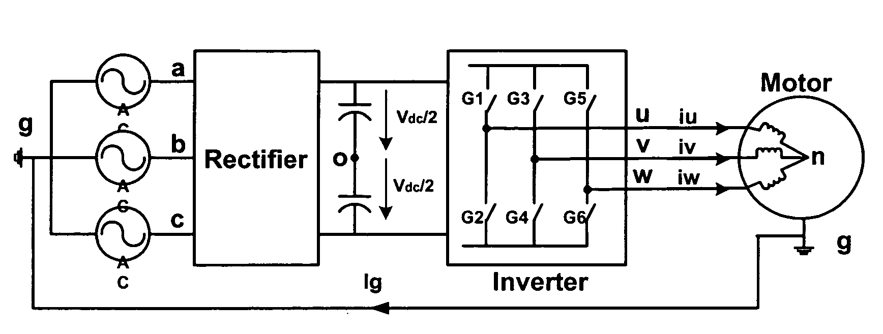
pulse width modulated (PWM) system that includes positive and negative DC links, at least one of a converter and an inverter that includes first, second and third upper switching devices that link each of the first, second and third phases to the positive DC link and first, second and third lower switching devices that link each of the first, second and third phases to the negative DC link, respectively, a three phase waveform generator that generates first, second and third modulating waveforms, a carrier
signal generator and a PWM generator that compares modulating waveforms and the carrier
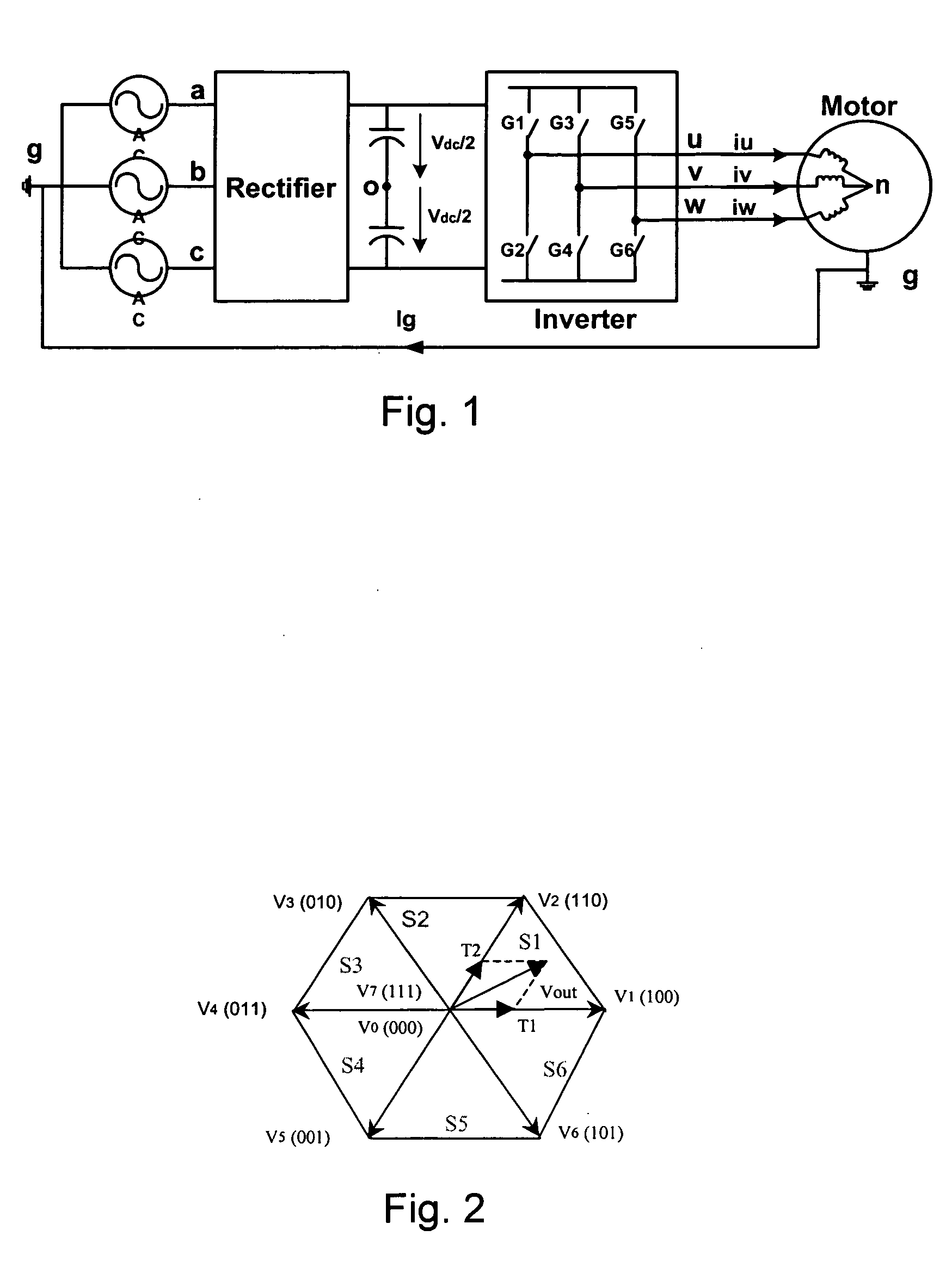
signal to generate switch control signals for controlling at least one of the converter and inverter switches, the switch control signals periodically commanding zero vectors V0 and V7 wherein each of the upper switches are on to link the three phases to the positive DC rail and where each of the lower switches are on to link the three phases to the negative DC rail, the method comprising the steps of receiving the first, second and third modulating waveforms, identifying the instantaneous maximum modulating waveforms as a first identified waveform, whenever the first, second and third modulating waveforms would result in a zero vector V0, generating switch control signals for the phase associated with the first identified waveform to connect the phase to the positive DC link and whenever the first, second and third modulating waveforms would result in a zero vector V7, generating switch control signals for the phase associated with the first identified waveform to connect the phase to the negative DC link.
[0022]Still other embodiments include a method for reducing common mode
noise in a three phase pulse width modulated (PWM) system that includes positive and negative DC links, at least one of a converter and an inverter that includes first, second and third upper switching devices that link each of the first, second and third phases to the positive DC link and first, second and third lower switching devices that link each of the first, second and third phases to the negative DC link, respectively, a three phase waveform generator that generates first, second and third modulating waveforms, a carrier
signal generator and a PWM generator that compares modulating waveforms and the carrier signal to generate switch control signals for controlling at least one of the converter and inverter switches, the switch control signals periodically commanding zero vectors V0 and V7 wherein each of the upper switches are on to link the three phases to the positive DC rail and where each of the lower switches are on to link the three phases to the negative DC rail, the method comprising the steps of receiving the first, second and third modulating waveforms, identifying the instantaneous minimum modulating waveforms as a first identified waveform, whenever the first, second and third modulating waveforms would result in a zero vector V0, generating switch control signals for the phase associated with the first identified waveform to connect the phase to the positive DC link and whenever the first, second and third modulating waveforms would result in a zero vector V7, generating switch control signals for the phase associated with the first identified waveform to connect the phase to the negative DC link.
[0024]Still other embodiments include an apparatus for reducing common mode
noise in a three phase pulse width modulated (PWM) system that includes positive and negative DC links, at least one of a converter and an inverter that includes first, second and third upper switching devices that link each of the first, second and third phases to the positive DC link and first, second and third lower switching devices that link each of the first, second and third phases to the negative DC link, respectively, a three phase waveform generator that generates first, second and third modulating waveforms, a carrier
signal generator and a PWM generator that compares modulating waveforms and the carrier signal to generate switch control signals for controlling at least one of the converter and inverter switches, the switch control signals periodically commanding zero vectors V0 and V7 wherein each of the upper switches are on to link the three phases to the positive DC rail and where each of the lower switches are on to link the three phases to the negative DC rail, the apparatus comprising a processor programmed to receive the first, second and third modulating waveforms, identify the instantaneous maximum modulating waveforms as a first identified waveform, whenever the first, second and third modulating waveforms would result in a zero vector V0, generate switch control signals for the phase associated with the first identified waveform to connect the phase to the positive DC link and whenever the first, second and third modulating waveforms would result in a zero vector V7, generate switch control signals for the phase associated with the first identified waveform to connect the phase to the negative DC link.
[0025]Some embodiments include an apparatus for reducing common mode noise in a three phase pulse width modulated (PWM) system that includes positive and negative DC links, at least one of a converter and an inverter that includes first, second and third upper switching devices that link each of the first, second and third phases to the positive DC link and first, second and third lower switching devices that link each of the first, second and third phases to the negative DC link, respectively, a three phase waveform generator that generates first, second and third modulating waveforms, a carrier
signal generator and a PWM generator that compares modulating waveforms and the carrier signal to generate switch control signals for controlling at least one of the converter and inverter switches, the switch control signals periodically commanding zero vectors V0 and V7 wherein each of the upper switches are on to link the three phases to the positive DC rail and where each of the lower switches are on to link the three phases to the negative DC rail, the apparatus comprising a processor programmed to receive the first, second and third modulating waveforms, identify the instantaneous minimum modulating waveforms as a first identified waveform, whenever the first, second and third modulating waveforms would result in a zero vector V0, generate switch control signals for the phase associated with the first identified waveform to connect the phase to the positive DC link and whenever the first, second and third modulating waveforms would result in a zero vector V7, generate switch control signals for the phase associated with the first identified waveform to connect the phase to the negative DC link.

