Sliding element

a technology of sliding element and sliding contact bearing, which is applied in the direction of sliding contact bearing, other domestic articles, reflex reflectors, etc., to achieve the effect of improving wear resistance, facilitating production, and increasing the orientation of crystallites

Inactive Publication Date: 2007-11-22
MIBA SINTER AUSTRIA
View PDF8 Cites 7 Cited by
  • Summary
  • Abstract
  • Description
  • Claims
  • Application Information

AI Technical Summary

Benefits of technology

[0014] In addition to being lead-free the main advantage of the sliding layer according to the invention is that it is easy to produce. This strong orientation according to the (012) plane is achieved for example by galvanic precipitation. There is no need for example, as proposed in DE 10 2004 015 827 A1, to work with reversing periods in a specific operating cycle. The sliding element according to the invention also has improved wearing resistance due to the strong orientation of the crystallites.
[0015] According to one embodiment variant the lattice plane with the second highest X-ray diffraction intensity is the one with the Miller index (024). In this way a greater degree of orientation of the crystallites in the sliding layer is achieved whereby the above properties are further improved.

Problems solved by technology

However, lead is undesirable due to its toxicity and, particularly recently, increasing attempts have been made to find ways of eliminating lead.

Method used


Image

  • Sliding element
  • Sliding element
  • Sliding element

Examples


example 1

Bath Composition for the Galvanic Precipitation

[0041] 50 g / l Bi as methane sulphonate [0042] 80 g / l methane sulphonic acid to improve conductivity [0043] Addition of smoothing agent and at least one tenside.

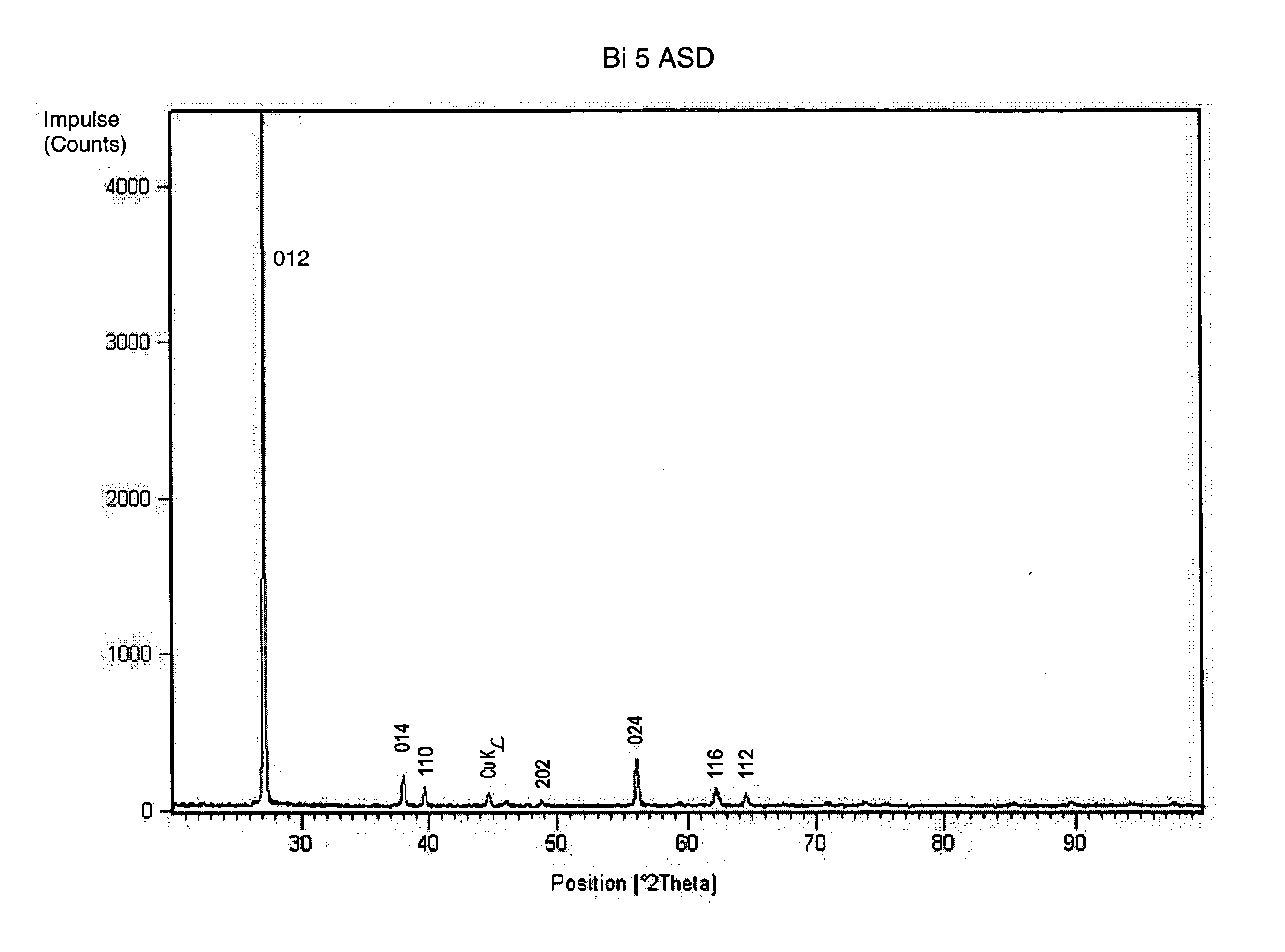
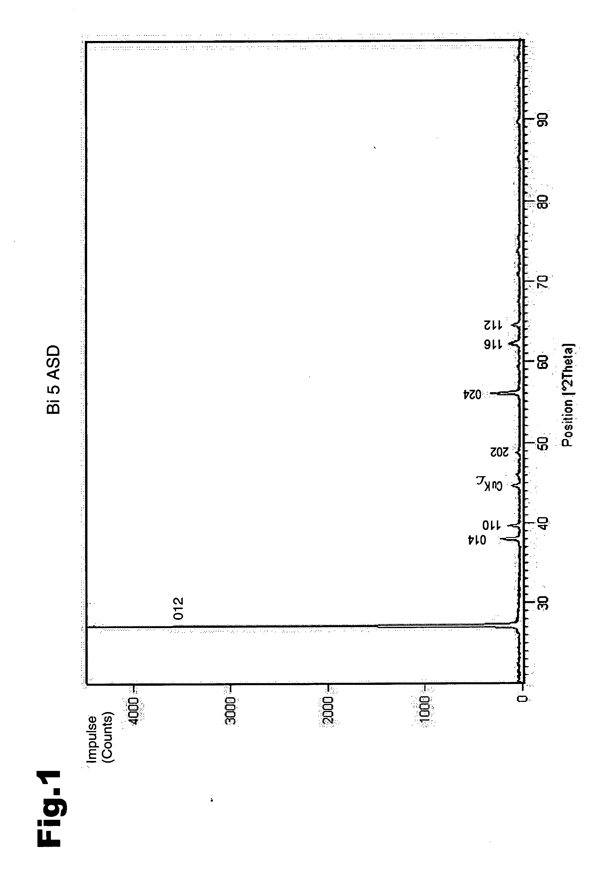
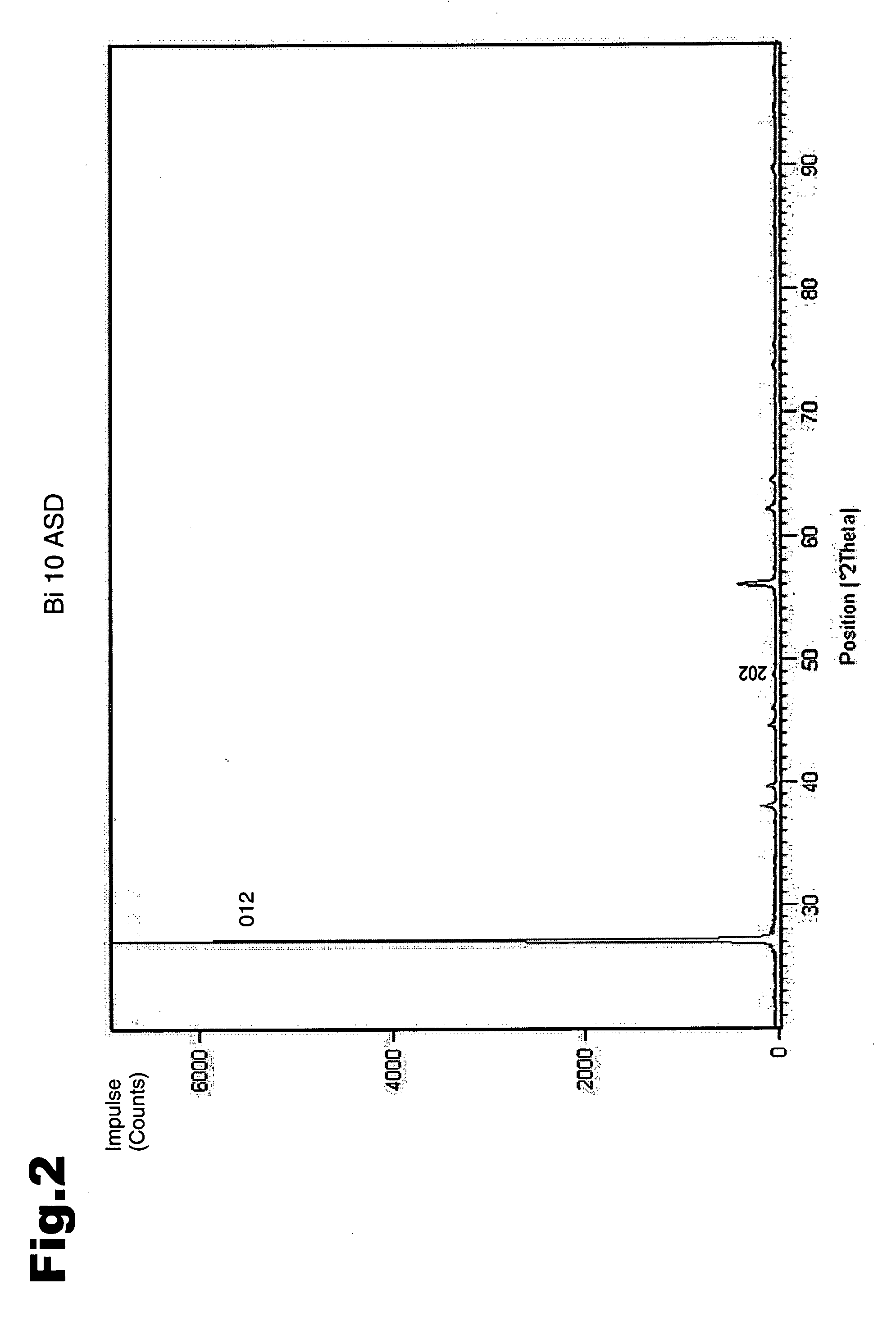
[0044] Operating Data: [0045] Room temperature [0046] Current density: 5 A / dm2 (FIG. 1) or 10 A / dm2 (FIG. 2) or 15 A / dm2 (FIG. 3)

example 2

Bath Composition for the Galvanic Precipitation

[0047] 70 g / l Bi as methane sulphonate [0048] 50 g / l methane sulphonic acid to improve conductivity [0049] 1 g / l commercially available tenside for improving wettability [0050] 0.5 g / l layer smoothing additive (“leveller”)

[0051] Operating Data: [0052] Room temperature [0053] Current density: 5 A / dm2

[0054] Of the sliding layers produced X-ray diffraction diagrams were then recorded which are shown in FIGS. 1 to 3. The corresponding intensities for FIG. 1 are given in Table 1.

PlaneIntensity012456101422311016120282024339116178112125

[0055] The readout corresponds to a standard readout, whereby on the x-axis the °2 theta values are entered and on the y-axis the impulses (counts) are entered. The readout was produced by a camera and CuKα-radiation was used.

[0056] As shown from the comparison of the three diagrams according to FIGS. 1 to 3, with an increase in the current density during the precipitation the 012 plane comes more clearly ...


PUM

PropertyMeasurementUnit
Vickers hardnessaaaaaaaaaa
thicknessaaaaaaaaaa

Abstract

The invention describes a sliding element, in particular a sliding bearing, with a support element and a sliding layer, between which a bearing metal layer is arranged, wherein the sliding layer is made from bismuth or a bismuth alloy, and wherein the crystallites of the bismuth or the bismuth alloy in the sliding layer adopt a preferred direction with respect to their orientation, expressed by the Miller index of the lattice plane (012), wherein the X-ray diffraction intensity of the lattice plane (012) is the greatest compared to the X-ray diffraction intensities of other lattice planes. The X-ray diffraction intensity of the lattice plane with the second-largest X-ray diffraction intensity is a maximum of 10% of the X-ray diffraction intensity of the lattice plane (012).

Description

CROSS REFERENCE TO RELATED APPLICATIONS [0001] Applicant claims priority under 35 U.S.C. §119 of AUSTRIAN Patent Application No. A 551 / 2006 filed on March 30, 2006. BACKGROUND OF THE INVENTION [0002] 1. Field of the invention [0003] The invention relates to a sliding element with a support element and a sliding layer, between which a bearing metal layer is arranged, wherein the sliding layer is made from bismuth or a bismuth alloy and wherein the crystallites of the bismuth or the bismuth alloy in the sliding layer adopt a preferred direction with respect to their orientation, expressed by the Miller index of the lattice plane (012), wherein the X-ray diffraction intensity of the lattice plane (012) is the greatest compared to the X-ray diffraction intensity of the other lattice planes, and a method for its production. [0004] 2. Prior Art [0005] Sliding bearings are characterised inter alia in that they have a relatively soft sliding layer in order to allow for adjustment to the sup...

Claims


Application Information

Patent Timeline
Patent Type & Authority Applications(United States)
IPC IPC(8): F16C17/00
CPCC25D3/54C25D7/10F16C33/12Y10S428/935Y02T10/865Y10T428/12681Y10S384/912F16C33/14F16C2223/70F16C33/06F16C17/00F16C33/02
Inventor RUMPF, THOMAS
Owner MIBA SINTER AUSTRIA
Why Eureka
Try Eureka