
Polarizing plate and image display including the same

a technology of image display and polarizing plate, which is applied in the direction of polarizing elements, thin material handling, instruments, etc., can solve the problems of polarization properties, and achieve the effects of high hardness, excellent optical properties, and high hardness

Inactive Publication Date: 2007-11-22
NITTO DENKO CORP
View PDF1 Cites 32 Cited by
  • Summary
  • Abstract
  • Description
  • Claims
  • Application Information

AI Technical Summary

Benefits of technology

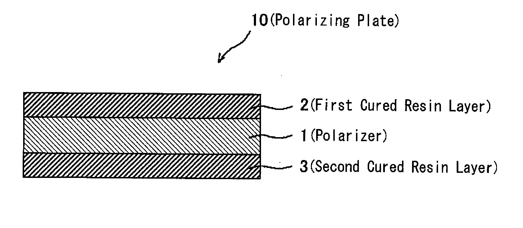
[0008] The present invention is intended to provide a polarizing plate that has a high hardness, can have a reduced thickness, and has excellent polarization properties, and an image display including the same.
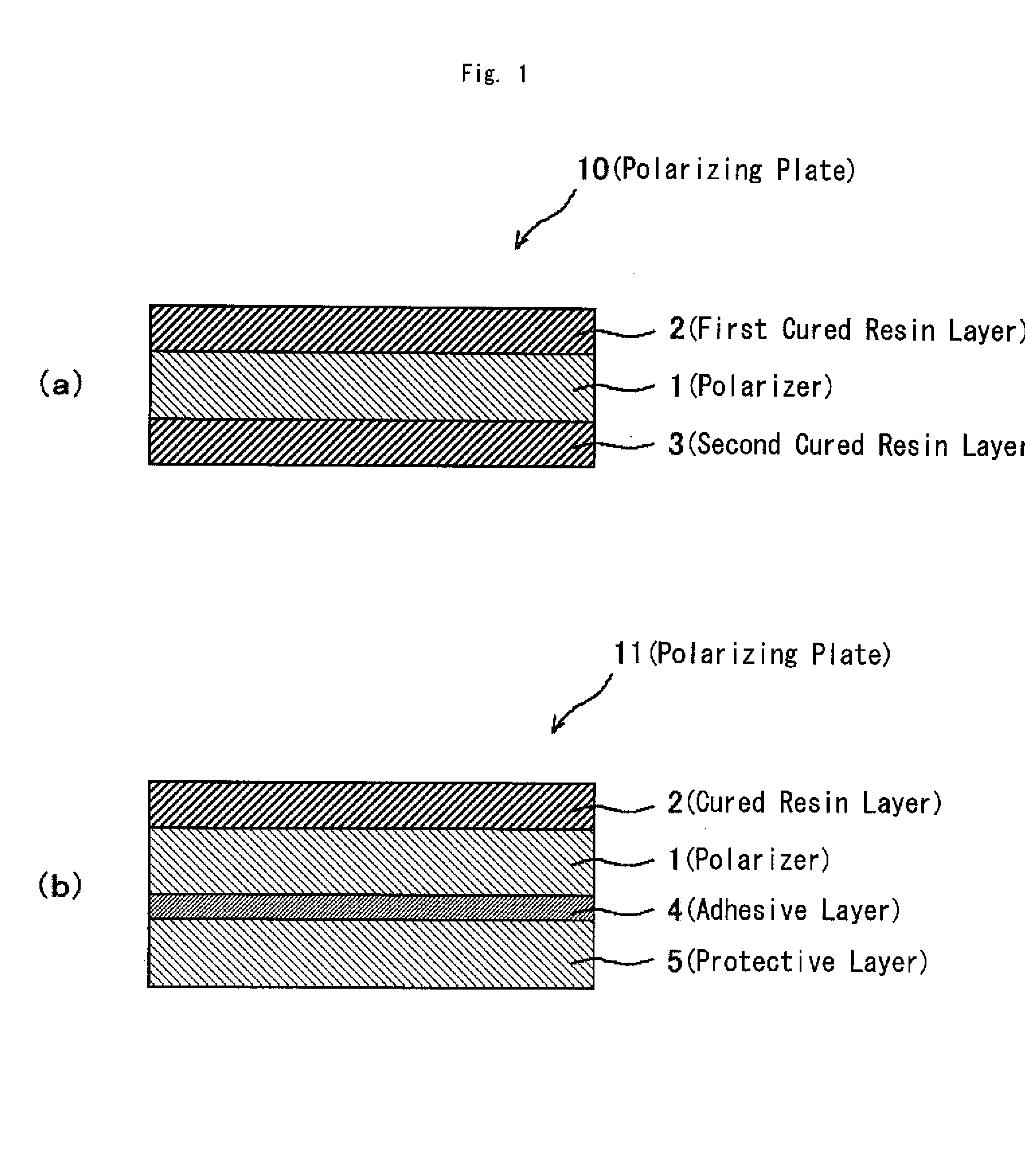
[0011] The present inventors made a series of studies with respect to the deterioration in properties of conventional polarizing plates in which a protective film was formed directly on a polarizer using a photocurable compound. As a result, it was found that the deterioration in properties resulted from erosion of a polarizer caused by a solvent used for forming the protective layer in the conventional polarizing plates. Based on this finding, it was further found that when a cured resin layer was formed directly on at least one surface of a polarizer using the solventless photocurable composition having the aforementioned composition, the properties of the polarizer were not deteriorated and a cured resin layer with a higher hardness than that of conventional hard-coating layers was formed. Thus the present invention was completed. The polarizing plate of the present invention has excellent optical properties, a higher hardness than that of conventional one, and can have a reduced thickness since the protective layer can be omitted.

Problems solved by technology

Moreover, the polarizing plate wherein the TAC film is omitted and a protective film is formed on the surface of a polarizer using a photopolymerizable compound to reduce the thickness, has a problem with polarization properties.

Method used


Image

  • Polarizing plate and image display including the same
  • Polarizing plate and image display including the same
  • Polarizing plate and image display including the same

Examples


example 1

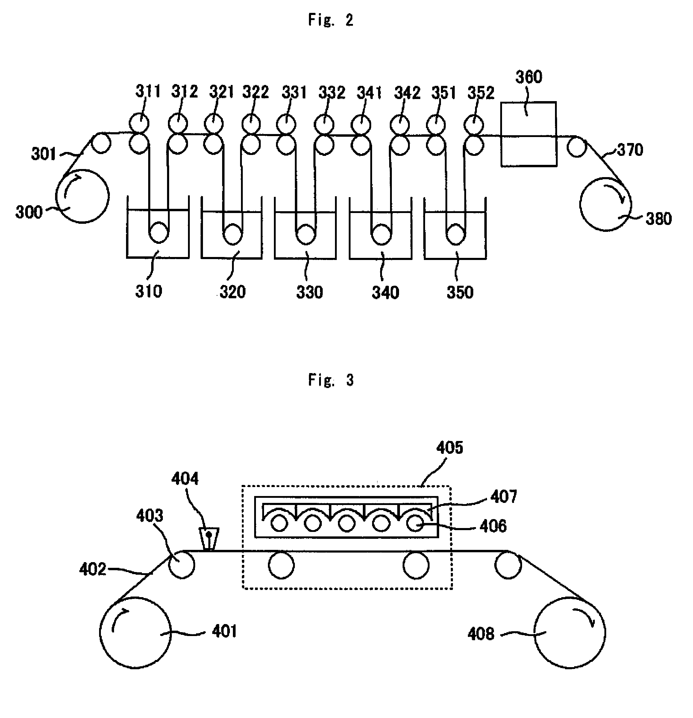
[0099] A polymer film (with a thickness of 75 μm, “VF-PS#7500” (trade name) manufactured by KURARAY CO., LTD.) whose main component was polyvinyl alcohol resin was immersed in five baths under the following conditions (1) to (5), while being tensioned in the longitudinal direction thereof. The film was drawn so that the final draw magnification was 6.2 times the original film length. This drawn film was dried for one minute in an air circulation drying oven with a temperature of 40° C. Thus a polarizer A with a thickness of 30 μm (with a composite elastic modulus of 10.9 GPa) was prepared. In this polarizer A, the contents of the respective elements were as follows: iodine content=3.0% by weight, potassium content=0.6% by weight, and boron content=2.0% by weight.

(1) Swelling bath: 30° C. pure water

(2) Dye bath: 30° C. aqueous solution containing 0.03 part by weight of iodine and 0.2 part by weight of potassium iodide, with respect to 100 parts by weight of water

(3) First cross...

example 2

[0103] A polarizing plate A-2 was produced in the same manner as in Example 1 except that the cured resin layer had a thickness of 10 μm. In the polarizing plate A-2, the transmittance, the polarization degree, and the composite elastic modulus of the cured resin layer were the same as those of Example 1. The pencil hardness of the cured resin layer surface of the polarizing plate A-2 was 7 H. After the polarizing plate A-2 was stored in a room at 23° C. for 24 hours, the state of the cured resin layer surface was observed visually. As a result, no cracks were observed at the cured resin layer surface.

example 3

[0104] A polarizing plate A-3 was produced in the same manner as in Example 1 except that the cured resin layer had a thickness of 15 μm. In the polarizing plate A-3, the transmittance, the polarization degree, and the composite elastic modulus of the cured resin layer were the same as those of Example 1. The pencil hardness of the cured resin layer surface of the polarizing plate A-3 was 9 H. After the polarizing plate A-3 was stored in a room at 23° C. for 24 hours, the state of the cured resin layer surface was observed visually. As a result, no cracks were observed at the cured resin layer surface.


PUM

PropertyMeasurementUnit
elastic modulusaaaaaaaaaa
thicknessaaaaaaaaaa
thicknessaaaaaaaaaa

Abstract

A polarizing plate is provided that has excellent polarization properties and high surface hardness and can have a reduced thickness. The polarizing plate includes a polarizer and a cured resin layer. The cured resin layer is formed directly on at least one surface of the polarizer. The cured resin layer is formed of a solventless photocurable composition containing the following components (A), (B), and (C): (A) at least one of a polyfunctional acrylic monomer and a polyfunctional methacrylic monomer; (B) a photocurable prepolymer; and (C) a photopolymerization initiator.

Description

CROSS-REFERENCE TO RELATED APPLICATIONS [0001] This application claims priority from Japanese Patent Application Nos. 2006-136943 filed on May 16, 2006 and 2007-102200 filed on Apr. 9, 2007 the entire contents of which are hereby incorporated by reference. BACKGROUND OF THE INVENTION [0002] 1. Field of the Invention [0003] The present invention relates generally to polarizing plates and image displays including the same. [0004] 2. Description of the Related Art [0005] A liquid crystal display (LCD) is one of the various image displays available. An LCD is a device that displays, for example, letters and images using electrooptic properties of liquid crystal molecules. Generally, an LCD is provided with a liquid crystal cell and two polarizing plates disposed on both sides of the liquid crystal cell. Generally, the polarizing plates each have a structure in which a protective film is attached to both sides of a polarizer with an adhesive. Conventionally, a triacetyl cellulose (TAC) f...

Claims


Application Information

Patent Timeline
Patent Type & Authority Applications(United States)
IPC IPC(8): C09K19/00G02B1/10G02B1/14G02B5/30G02F1/1335
CPCG02B5/3033Y10T428/10Y10T428/1036Y10T428/1041C09K2323/03C09K2323/031C09K2323/00G02B5/30C08J5/18
Inventor NAKANO, SHINYAHARA, KAZUTAKAFUCHIDA, TAKEHITOOOE, NAOTO
Owner NITTO DENKO CORP
Learn More