Acid Liquid Leakage Sensor

Active Publication Date: 2007-11-29
NTT FACILITIES INC +1
View PDF5 Cites 32 Cited by
  • Summary
  • Abstract
  • Description
  • Claims
  • Application Information

AI Technical Summary

Benefits of technology

[0020] Furthermore, it is desirable further to include a notification means which operates by change of the electrical conduction state, or by elect

Problems solved by technology

When this short circuit is created, a large current flows through the portion which has become electrically conducting due to the battery fluid 12, and sparking may occur, which is undesirable.
However, even if the case 11 is made from a resin, nevertheless, if liquid leakage has occurred from a plu

Method used


Image

  • Acid Liquid Leakage Sensor
  • Acid Liquid Leakage Sensor
  • Acid Liquid Leakage Sensor

Examples


first embodiment

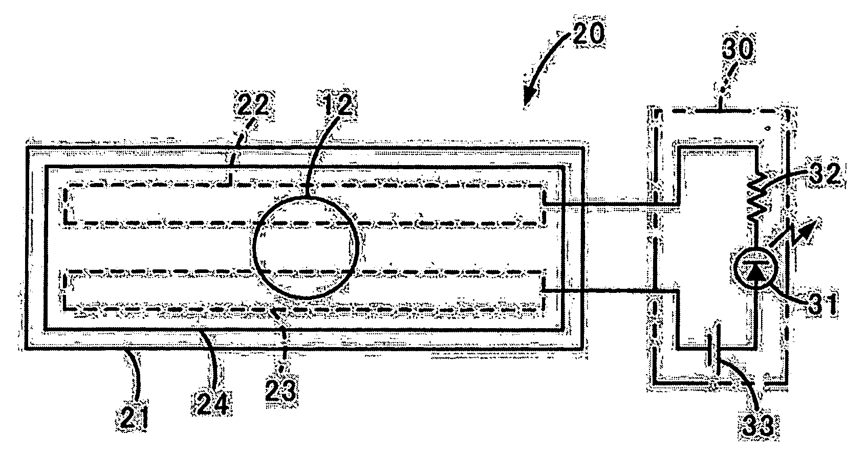
[0033]FIG. 1 is a plan view showing the upper surface of an example of a battery liquid leakage sensor, which is an acid liquid leakage sensor according to the present invention. This battery liquid leakage sensor 20 has a schematic structure which comprises: a base member 21 of sheet form; a first electrically conductive member 22 and a second electrically conductive member 23, both of band form, and arranged in parallel with a gap between them; a covering layer 24 which covers the surface of the base member 21 over each of the first conductive member 22 and the second conductive member 23, and which ensures that the first conductive member 22 and the second conductive member 23 are electrically insulated from one another or are separated by a high resistance; and a notification device 30 (a notification means) which is connected by lead wires to the first conductive member 22 and the second conductive member 23.

[0034] The notification device 30 has a schematic structure which com...

second embodiment

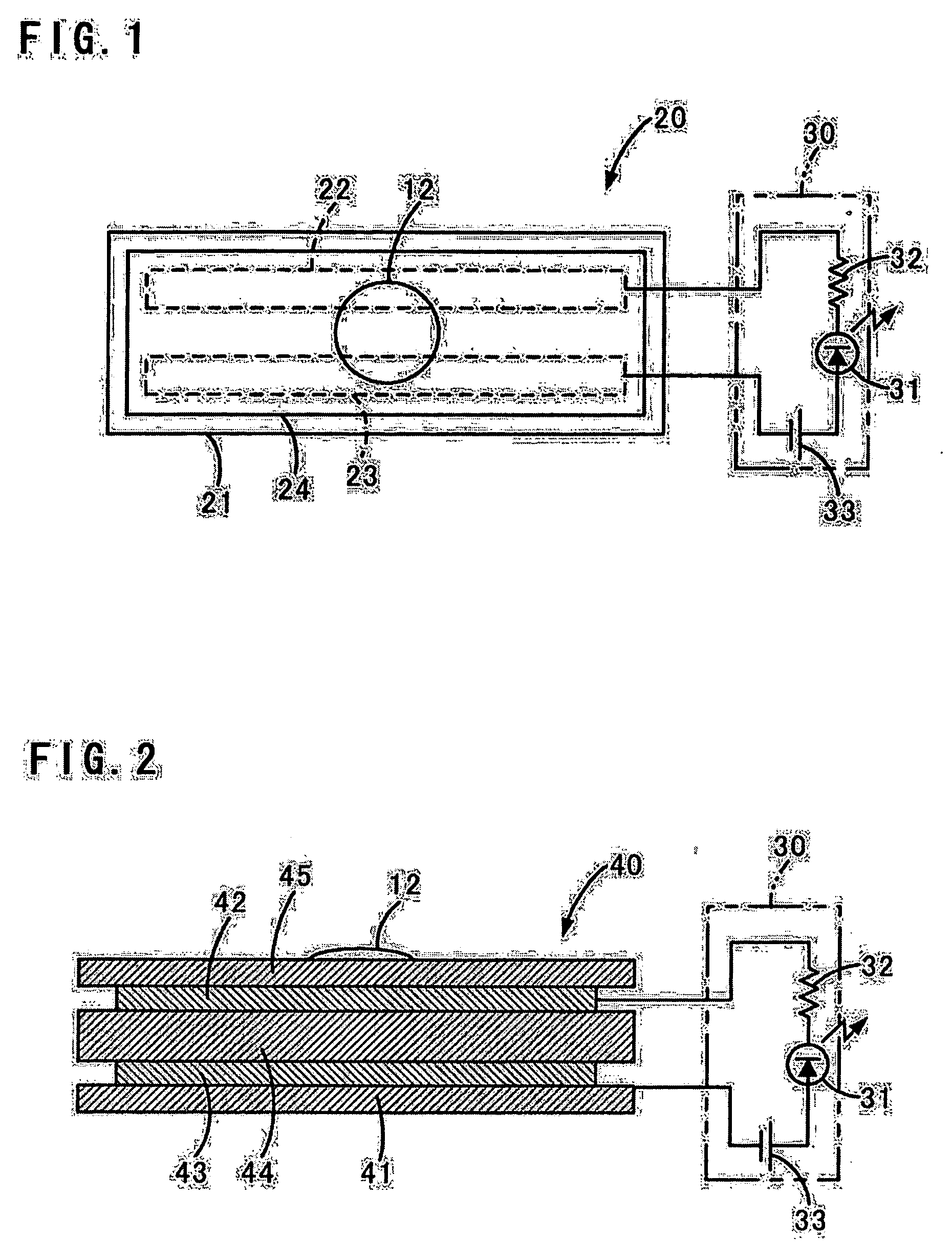
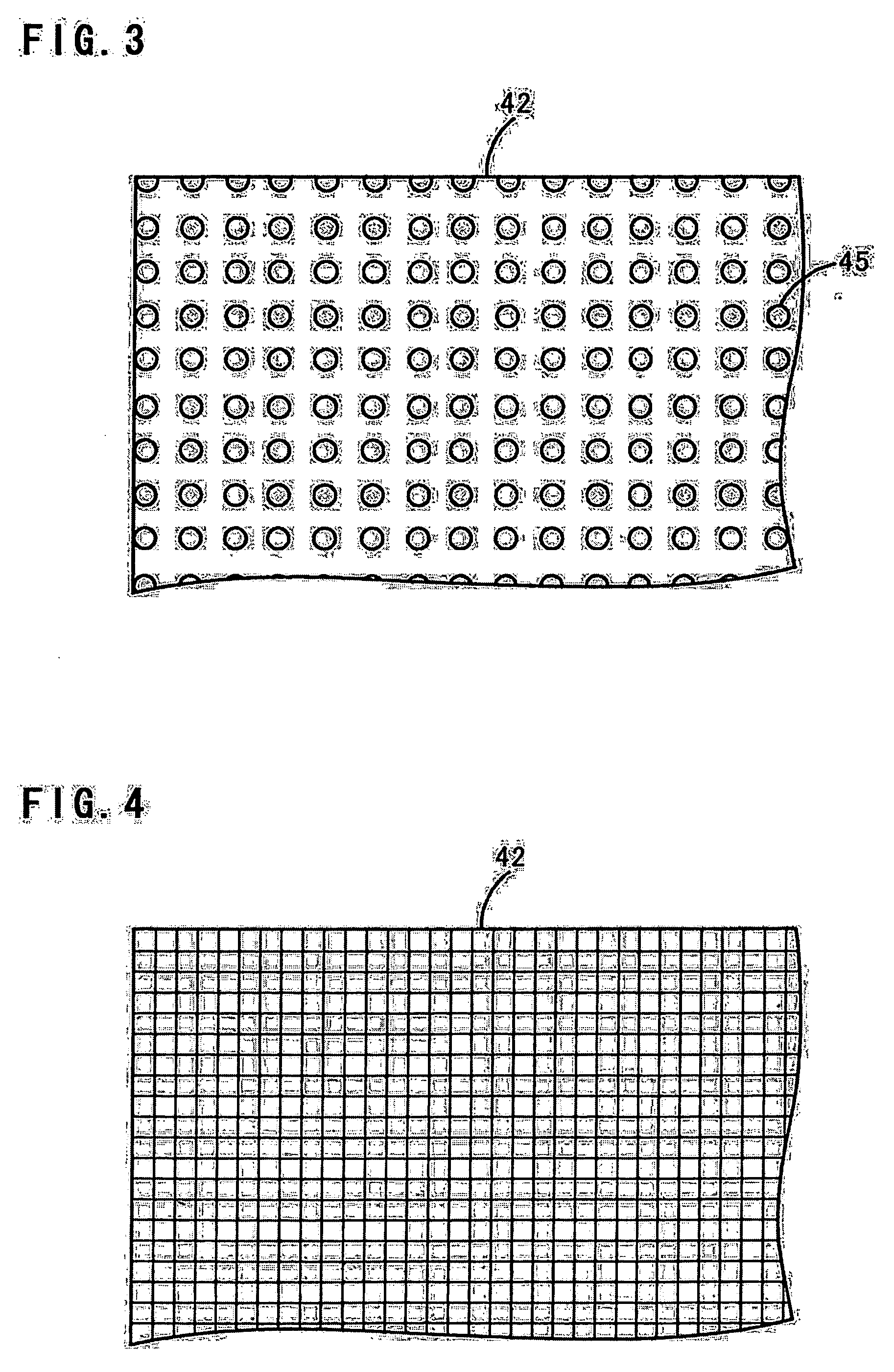
[0064]FIG. 2 is a sectional side view showing another fundamental example of a battery liquid leakage sensor, which is an acid liquid leakage sensor according to the present invention. This battery liquid leakage sensor 40 has a schematic structure comprising: a base member 41 of sheet form; a first conductive layer member 42 which is permeable to battery fluid (acid liquid); a second conductive layer member 43, an adhesive layer 44 which is interposed between the first conductive layer member 42 and the second conductive layer member 43, and which adheres between these members in an electrically insulating state or a high resistance state; a covering layer 45 which covers over the surface of the first conductive layer member 42; and a notification device 30 (a notification means) which is connected to the first conductive layer member 42 and the second conductive layer member 43. In other words, one distinguishing feature of this second embodiment is that the adhesive layer 44 is u...

third embodiment

[0078]FIG. 5 is a plan view showing the upper surface of a battery liquid leakage sensor 50 which is a third embodiment of the acid liquid leakage sensor of the present invention. The distinguishing feature of this battery liquid leakage sensor is that the previously described first conductive member and second conductive member are respectively made as a first comb shaped electrode 52 and a second comb shaped electrode 53.

[0079] This battery liquid leakage sensor 50 may, for example, have a schematic structure which comprises: a base member 51 in sheet form, about 80 cm×60 cm; a first comb shaped electrode 52 and a second comb shaped electrode 53 (see FIG. 6) each of which is shaped in the general form of a comb and is made on the surface of the base member 51; a covering layer 54 which covers the surface of the base member 51 and extends over both of the first comb shaped electrode 52 and the second comb shaped electrode 53, and which maintains a state of electrical insulation or...


PUM

PropertyMeasurementUnit
Lengthaaaaaaaaaa
Lengthaaaaaaaaaa
Fractionaaaaaaaaaa

Abstract

An acid liquid leakage sensor quickly detecting liquid leakage from a device, such as a battery or the like, containing an acid liquid includes a first conductive member, a second conductive member, and an electrically insulating material which establishes an electrically insulating state between these first and second conductive members. The electrically insulating material includes a macromolecular compound having a basic functional group, and an electrical insulation characteristic or high resistance characteristic that decreases upon reaction with an acid liquid. It is possible to detect leakage of acid liquid, such as battery fluid, by detecting the change of conductive state between the first conductive member and the second conductive member which accompanies a decrease of the electrical insulation characteristic or high resistance characteristic of the electrically insulating material, when acid liquid leaks out and drips down the electrically insulating material.

Description

TECHNICAL FIELD [0001] The present invention relates to an acid liquid leakage sensor which detects leakage of an acid liquid such as battery fluid or the like. BACKGROUND ART [0002] From the past, batteries such as lead-acid batteries and the like have been used as power supplies for various types of device. Dilute sulfuric acid is filled into these batteries as battery fluid. [0003]FIG. 11 is a figure showing an example of an uninterruptible power supply which employs a battery. The schematic structure of this uninterruptible power supply is that it comprises a rectification circuit 2 which is connected to the commercial AC power supply 1, a switching circuit 3 which is connected to the output side of the rectification circuit 2, and a plurality of batteries 10 in series, likewise connected to the output side of the rectification circuit 2. The switching circuit 3 is a device which converts the output voltage of the rectification circuit 2 or the voltage of the batteries 10 by swi...

Claims


Application Information

Patent Timeline
IPC IPC(8): H01M2/00G01M3/04G01M3/16G01M3/18G01N27/04G01N27/12G01N27/416H01M10/06H01M10/42H01M10/48
CPCH01M10/48G01M3/045G01M3/16H01M10/4228G01M3/186H01M10/06G01M3/165Y02E60/10
Inventor UEDA, TAKEHARUSATOH, KUNIHISASATO, KEIICHIKIYOKAWA, ICHIROTSUJIKAWA, TOMONOBUMATSUSHIMA, TOSHIO
Owner NTT FACILITIES INC
Why Eureka
Try Eureka