

Anti-aeration system for a suspension actuator
- Summary
- Abstract
- Description
- Claims
- Application Information
AI Technical Summary
Benefits of technology
Problems solved by technology
Method used
Image

Examples
Embodiment Construction
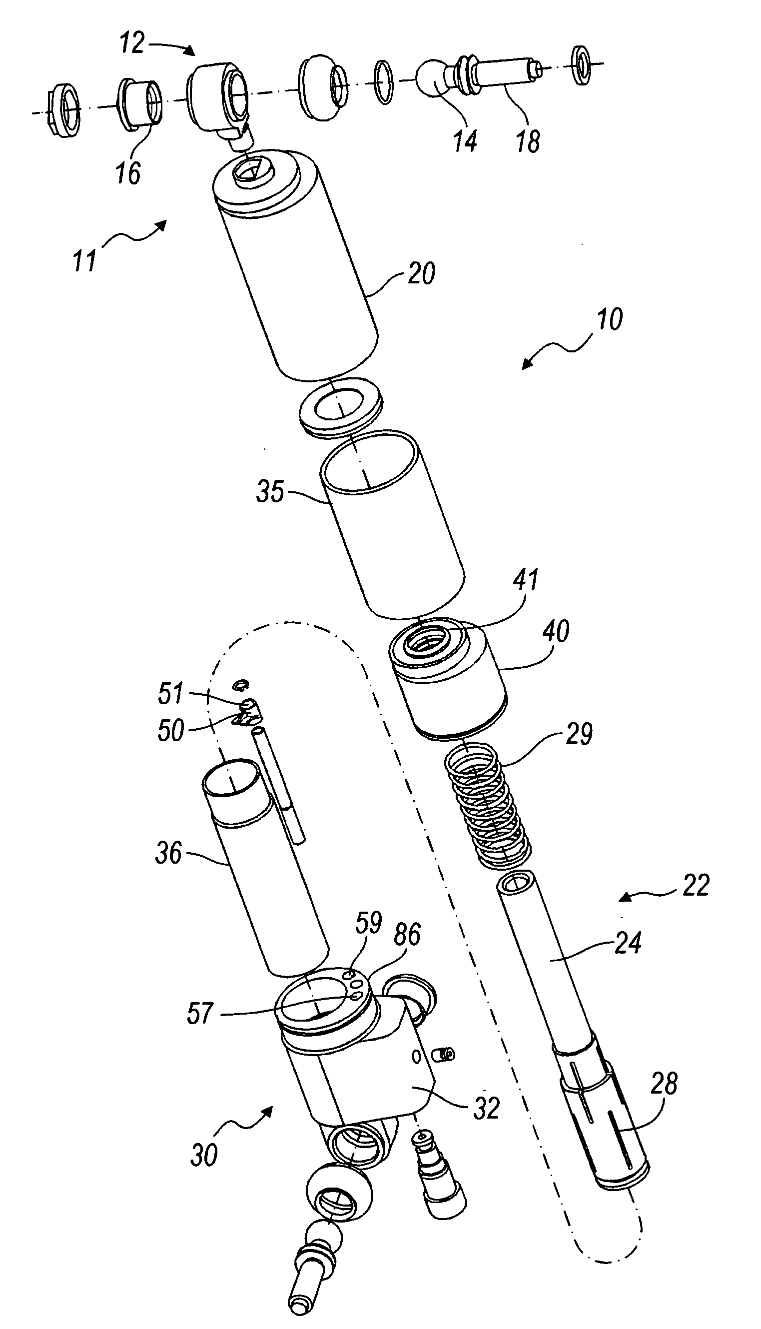
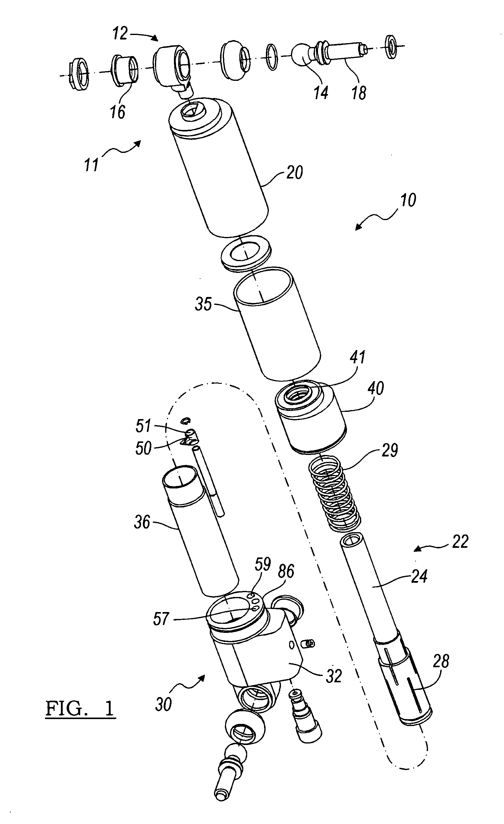
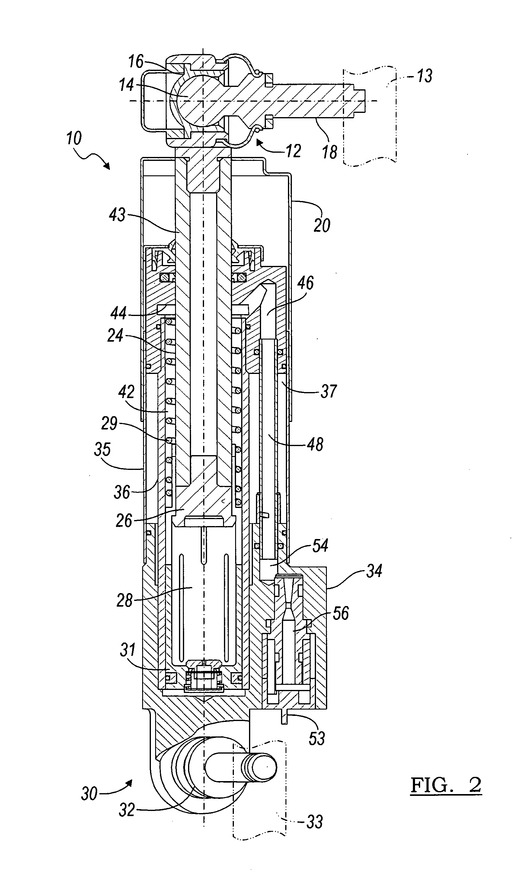
[0028]Referring now to the drawings, there is illustrated in FIGS. 1 and 2 a self-contained hydraulic fluid actuator 10 for a semi-active roll control system. The actuator 10 includes an upper mount assembly 11 for attachment to a first mass 13 of a vehicle such as a vehicle frame member. The upper mount assembly 11 includes an upper ball joint assembly 12 having a pivot ball 14 interconnected to a socket 16 which allows for circumferential movement of the actuator 10 in relation to the attaching vehicle frame member. The pivot ball 16 is also coupled to a pivot shaft 18 for attachment to the vehicle frame member.
[0029]The upper mount assembly 11 also includes a dust cover 20. The dust cover 20 functions as a protective guard against debris (e.g., stones) from the road that may cause damage to any underlying components of the actuator 10. A piston assembly 22 is also coupled to the upper mount assembly 11. The piston assembly 22 includes a piston rod 24, a piston rod head 26, a pist...
PUM
 Abstract
Description
Claims
Application Information