Anode for use in aluminum producing electrolytic cell

an electrolytic cell and anode technology, applied in the field of anodes, can solve the problem of unfavorable metal distribution on complex shaped workpieces

Inactive Publication Date: 2007-12-06
NORTHWEST ALUMINUM TECH LLC
View PDF33 Cites 38 Cited by
  • Summary
  • Abstract
  • Description
  • Claims
  • Application Information

AI Technical Summary

Benefits of technology

[0024]Thus, an anode which is comprised of a Cu—Ni—Fe—Sn alloy is provided for use in an electrolytic cell for producing aluminum from alumina dissolved in a molten salt electrolyte contained in the cell. The cell contains at least one cathode and one anode disposed in the electrolyte, the cathode having a planar surface. The anode has a substantially flat first surface for disposing opposite the cathode planar surface to provide a con

Problems solved by technology

According to known methods using soluble anodes and applying direct current,

Method used


Image

  • Anode for use in aluminum producing electrolytic cell
  • Anode for use in aluminum producing electrolytic cell
  • Anode for use in aluminum producing electrolytic cell

Examples


example 1

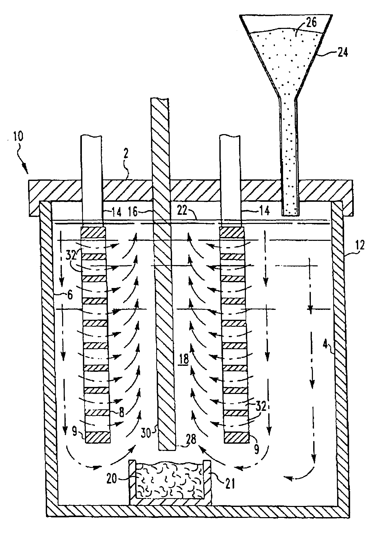
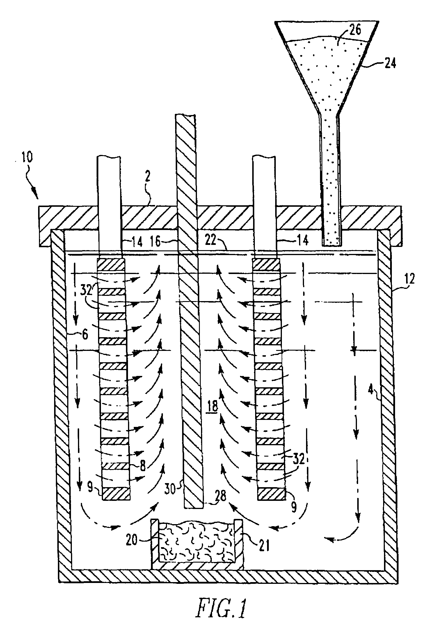
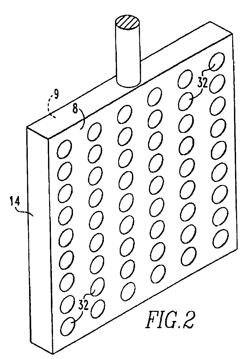
[0058]This invention was tested in a 150 A cell having the configuration shown in FIG. 1 with alumina added to the cell substantially continuously. The cell comprised an alumina ceramic container. Within the ceramic container was placed a vertical cathode suspended through the lid of the container and connected to a bus bar. On either side of the cathode, two anodes were positioned or suspended through the lid and connected to bus bar. The anodes were 4 inches by 5 inches by ⅜ inch thick. Each anode was drilled to provide 112 holes ¼ inch in diameter. The anodes were comprised of 18 wt. % Cu, 20 wt. % Ni, 2 wt. % Sn and 60 wt. % Fe, and the cathode was TiB2. The cell contained a molten salt bath comprised of 37.93 wt. % sodium fluoride and 62.07 wt. % aluminum fluoride. The top of the cell was sealed with an insulating lid and the cell was maintained at an operating temperature of 770° to 780° C. which was above the melting point of the salt bath and the aluminum metal. The alumina ...

example 2

[0059]A second test was run for 503 hours. The composition of the anode was the same as in Example 1. The operating temperature was 800° C., the current density was 0.53 amps / cm2, and the ACD was one inch. The average voltage for the entire run was 4.08 volts and was steady at the completion of the run. Smelter grade alumina was used. The melt purity was 99.83% for the entire test. This included impurities from the alumina.

[0060]The use of the new anode results in reduced voltage due to reduced surface oxide layer resistance compared to anodes using only Cu—Ni—Fe. Further, the new anode permits increased usage of lower cost iron as the primary alloying component. Also, compared to a Cu—Ni—Fe anode, the use of Cu—Ni—Fe—Sn results in long term stabililty of the surface oxide layer. In addition, the new Cu—Ni—Fe—Sn anode results in better metal purity. Furthermore, the Cu—Ni—Fe—Sn anode results in improved corrosion resistance at the cell bath interface, eliminating the need for extra ...


PUM

PropertyMeasurementUnit
Temperatureaaaaaaaaaa
Angleaaaaaaaaaa

Abstract

A method of producing aluminum in an electrolytic cell containing alumina dissolved in an electrolyte, the method comprising the steps of providing a molten salt electrolyte at a temperature of less than 900° C. having alumina dissolved therein in an electrolytic cell having a liner for containing the electrolyte, the liner having a bottom and walls extending upwardly from said bottom. A plurality of non-consumable Cu—Ni—Fe—Sn anodes and cathodes are disposed in a vertical direction in the electrolyte, the cathodes having a plate configuration and the anodes having a flat configuration to compliment the cathodes. The anodes contain apertures therethrough to permit flow of electrolyte through the apertures to provide alumina-enriched electrolyte between the anodes and the cathodes. Electrical current is passed through the anodes and through the electrolyte to the cathodes, depositing aluminum at the cathodes and producing gas at the anodes.

Description

BACKGROUND OF THE INVENTION[0001]This invention relates to aluminum and more particularly it relates to an improved anode for use in the electrolytic production of aluminum from alumina dissolved in a molten salt electrolyte.[0002]There is great interest in using an inert anode in an electrolytic cell for the production of aluminum from alumina dissolved in the molten salt electrolyte. By definition, the anode should not be reactive with the molten salt electrolyte or oxygen generated at the anode during operation. Anodes of this general type are disclosed in U.S. Pat. Nos. 4,592,812; 4,865,701; 5,006,209; 5,284,562; 6,558,525; 6,723,222; 6,800,191; 6,811,676 and 6,837,982. Examples of other such anodes of this type are comprised of a cermet. For example, U.S. Pat. No. 4,399,008 discloses a composition suitable for fabricating into an inert electrode for use in the electrolytic production of metal from a metal compound dissolved in a molten salt. The electrode comprises at least two...

Claims


Application Information

Patent Timeline
IPC IPC(8): C25C3/06C25B11/04C25C3/08
CPCC25C3/12C25C3/06
Inventor BARNETT, ROBERT J.BALLINGER, JAMES R.
Owner NORTHWEST ALUMINUM TECH LLC
Why Eureka
Try Eureka