Ion mobility spectrometer apparatus and methods

a technology ion spectrometer, which is applied in the direction of mass spectrometers, instruments, separation processes, etc., can solve the problems of increasing the cost limiting the performance of ion mobility spectrometer, and the probability of technical problems of drift tubes, etc., to achieve rapid temperature modulation, increase the temperature of drift tubes, and simple construction

Active Publication Date: 2007-12-06
EXCELLIMS CORP
View PDF12 Cites 30 Cited by
  • Summary
  • Abstract
  • Description
  • Claims
  • Application Information

AI Technical Summary

Benefits of technology

[0007] In addition to forming the electric field, the helical resistive coil can increase the temperature of the drift tube and any gases flowing through the drift tube. In some embodiments of the ion mobility spectrometer of the present invention, the drift tube temperature is controlled by using the helical resistive coil and a heating element that preheats the drift gas to the designed temperature. The drift gas is delivered directly inside the coil and pumped away from the gas outlet on the protective housing. This configuration provides a robust ion mobility spectrometer that is simple to build with lower thermal mass along the ion and drift gas path, thus allowing rapid temperature modulation, which is required by some applications.
[0008] One feature of the present invention is that the drift tube design described herein enables the ion mobility spectrometer to be built with a lower weight, lower power consumption, lower manufacturing cost, and free of sealants that may out gas. In addition, the drift tube can be isolated from ambient environment using vacuum sealing methods that can sustain pressure levels greater than atmospheric pressure.
[0009] In addition, the ion mobility spectrometer configuration described herein provides a means to rapidly change pressure inside of the drift tube during the ion mobility measurement. The resistance coil based drift tube configuration allows operating time-of-flight type IMS under high electric field conditions. Measuring ion mobilities of the same ionic species under both high and low field conditions (E / p ratio) provide additional information for ion identification. Unresolved ion mobility peaks under low field conditions may be separated and identified under high field conditions. Methods of sequentially measuring ion mobilities under different E / p ratio according to the present invention allows correlating low field and high field mobilities for comprehensive ion identification.

Problems solved by technology

Such complex mechanical designs significantly increase the cost of ion mobility spectrometer and can also limit the performance of the ion mobility spectrometer.
In general, the more parts in the drift tube design, then the higher probability that the drift tube will have technical problems, such as gas leakage, inadequate temperature control, inadequate pressure control, thermal and / or electrical insulation leakage.
However, “baking out” typically takes hours to complete.
However, the more drift rings that are used in a drift tube, the more lead wires are needed to be sealed at the wall to complete the drift tube structure.
Structure complication greatly limits the possibility of creating highly uniform electric fields in the drift tube.
However, coatings that are exactly the same thickness along the drift tube are a very challenging to make.
Conductive layers with uneven coating thickness will cause distorted electric field distributions and unpredictable system performance.

Method used


Image

  • Ion mobility spectrometer apparatus and methods
  • Ion mobility spectrometer apparatus and methods
  • Ion mobility spectrometer apparatus and methods

Examples


Embodiment Construction

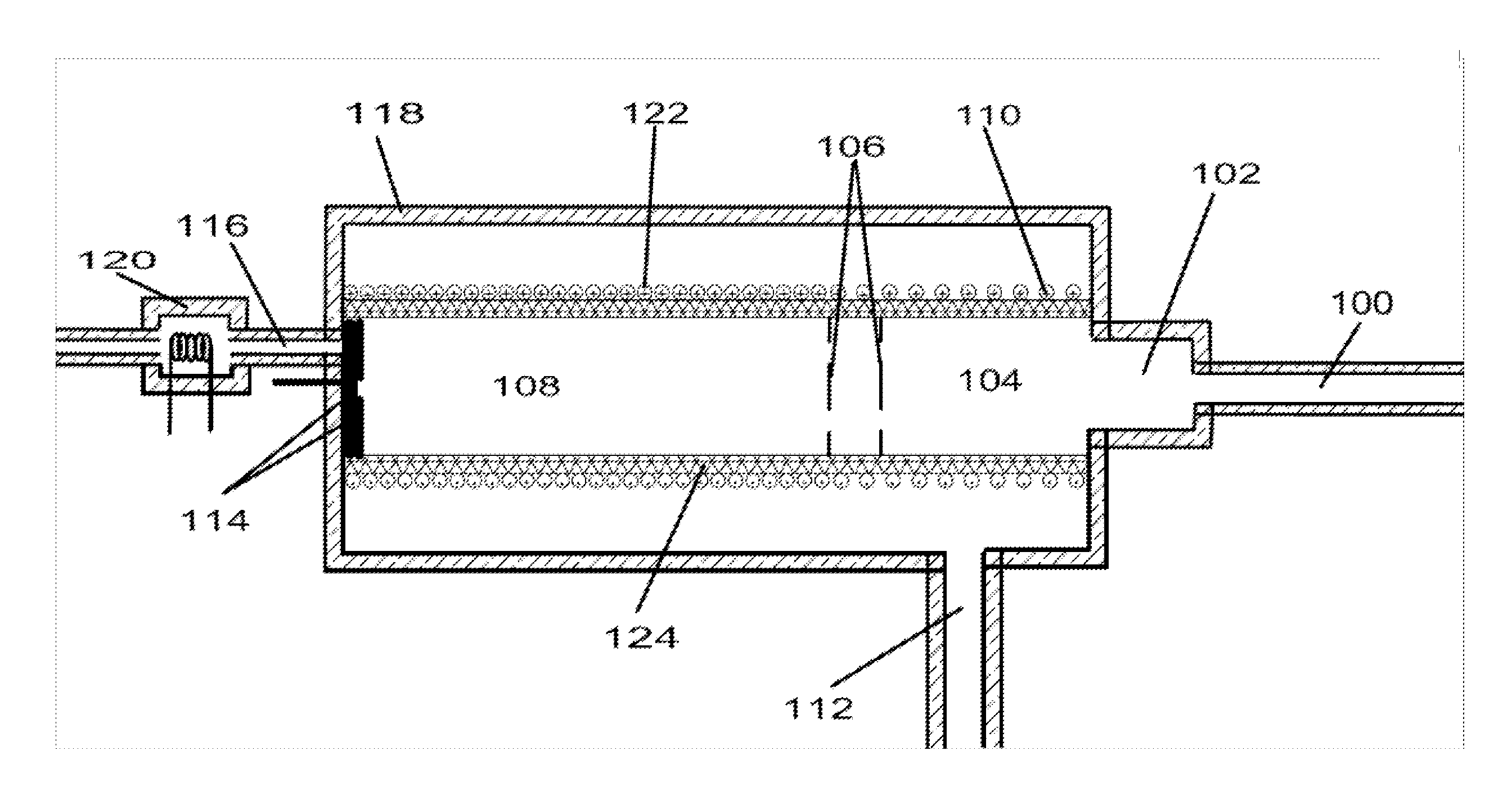
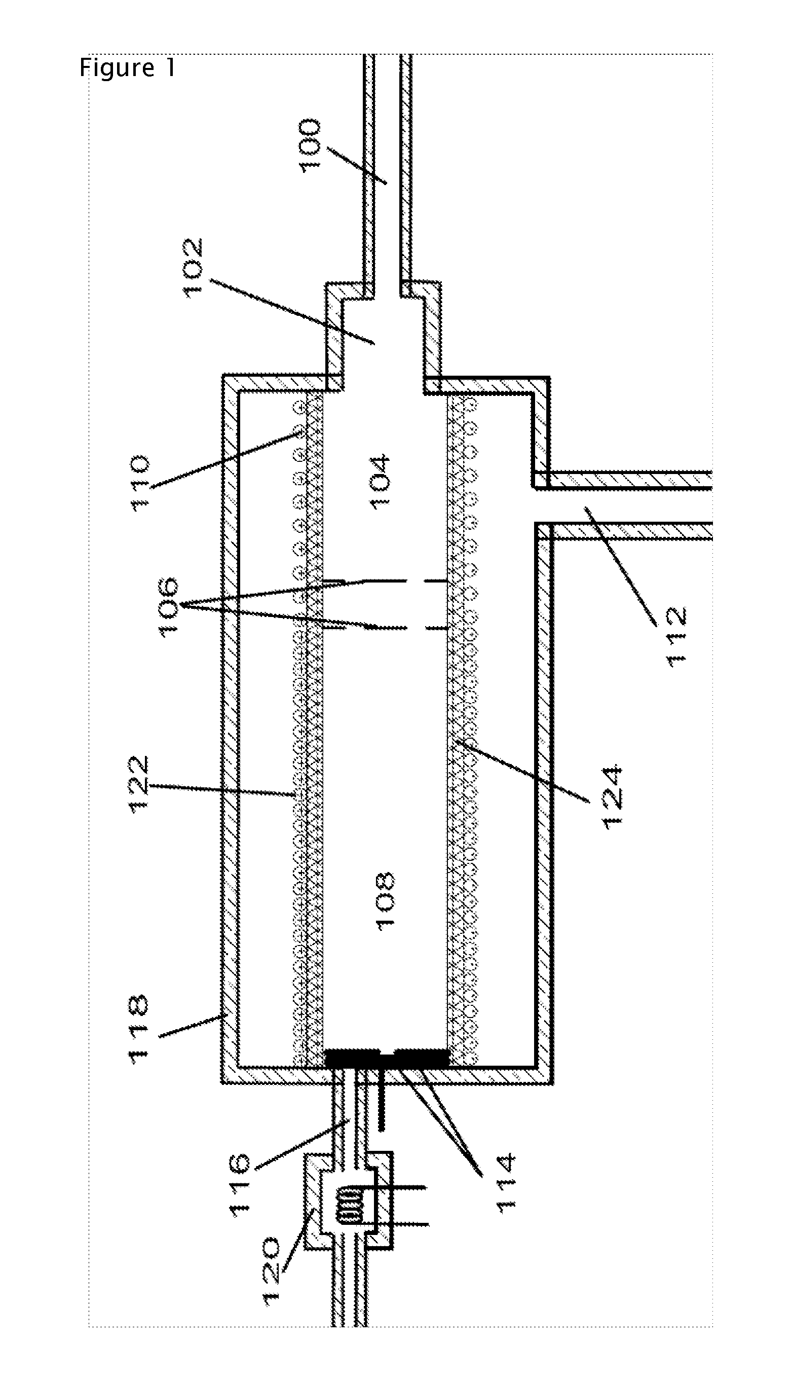
[0018]FIG. 1 illustrates a schematic diagram of an embodiment of the ion mobility spectrometer of the present invention. The sample is introduced to the spectrometer through a sample inlet 100. The sample is ionized while it passes through the ionization source 102. The ionization process is completed in the reaction region 104 before reaching the ion gate assembly 106. In various embodiments, the ion mobility spectrometer described herein can also sample chemicals in ionic form and / or from an external ionization source. The ion gate assembly 106 includes either a Bradbury-Nielsen gate or multiple grids that generate a narrow pulse of ions that is introduce into the drift region 108. Both the reaction region 104 and the drift region 108 of the drift tube are guarded with ion guides.

[0019] The ion guides of the present invention are made of a single or a plurality helical coil of resistance wires. The coil of resistance wires used in the reaction region and in drift region can be th...


PUM

PropertyMeasurementUnit
electric field strengthaaaaaaaaaa
lengthaaaaaaaaaa
lengthaaaaaaaaaa

Abstract

An ion mobility spectrometer includes a protective housing. A drift tube having at least one inlet and at least one outlet confines a drift gas. An ion gate is positioned in the drift tube. The ion gate defines a reaction region and a drift region in the drift tube. An ion detector is positioned in the drift tube downstream of the ion gate at an end of the drift region. A helical resistive wire coil is positioned around the drift tube. A power supply generates an electric field in the helical resistive wire coil that rapidly controls the temperature of the drift gas.

Description

CROSS-REFERENCE TO RELATED APPLICATIONS [0001] The present application claims the benefit of and priority to corresponding U.S. Provisional Patent Application No. 60 / 766,825, filed Feb. 14, 2006, the entire content of which is herein incorporated by reference.BACKGROUND OF THE INVENTION [0002] The basic components of a typical ion mobility spectrometer (IMS) include an ionization source, a drift tube that includes a reaction region, an ion shutter grid, a drift region, and an ion detector. In gas phase analysis, the sample to be analyzed is introduced into the reaction region by an inert carrier gas, ionization of the sample is often accomplished by passing the sample through a reaction region and / or an ionization region. The generated ions are directed toward the drift region by an electric field that is applied to drift rings (sometime referred as guard rings or ion guide) that establish the drift region. A narrow pulse of ions is then injected into, and / or allowed to enter, the d...

Claims


Application Information

Patent Timeline
Patent Type & Authority Applications(United States)
IPC IPC(8): G01N27/64H01J49/40
CPCG01N27/622H01J49/062
Inventor WU, CHING
Owner EXCELLIMS CORP
Why Eureka
Try Eureka