Wavelength conversion member and light-emitting device

a technology of wavelength conversion and light-emitting device, which is applied in the direction of discharge tube/lamp details, discharge tube luminescent screen, discharge tube/lamp details, etc., can solve the problems of insufficient effect in terms of incident efficiency of excitation light on phosphors and extraction efficiency of fluorescence from phosphor particles, so as to improve wavelength conversion efficiency, improve luminous efficacy, and improve the effect of incident efficiency of excitation ligh

Active Publication Date: 2007-12-06
XIAMEN SANAN OPTOELECTRONICS CO LTD
View PDF6 Cites 79 Cited by
  • Summary
  • Abstract
  • Description
  • Claims
  • Application Information

AI Technical Summary

Benefits of technology

[0030]The wavelength conversion member according to the present invention achieves improvement in incident efficiency of excitation light on the phosphors and extraction efficiency of fluorescence from the phosphors, and hence achieves improvement in wavelength conversion effi

Problems solved by technology

When a large difference exists between a refractive index of the phosphors and a refractive index of a medium made of resin, glass, or the like for holding the phosphors in a dispersed

Method used


Image

  • Wavelength conversion member and light-emitting device
  • Wavelength conversion member and light-emitting device
  • Wavelength conversion member and light-emitting device

Examples


example 1

Wavelength Conversion Member

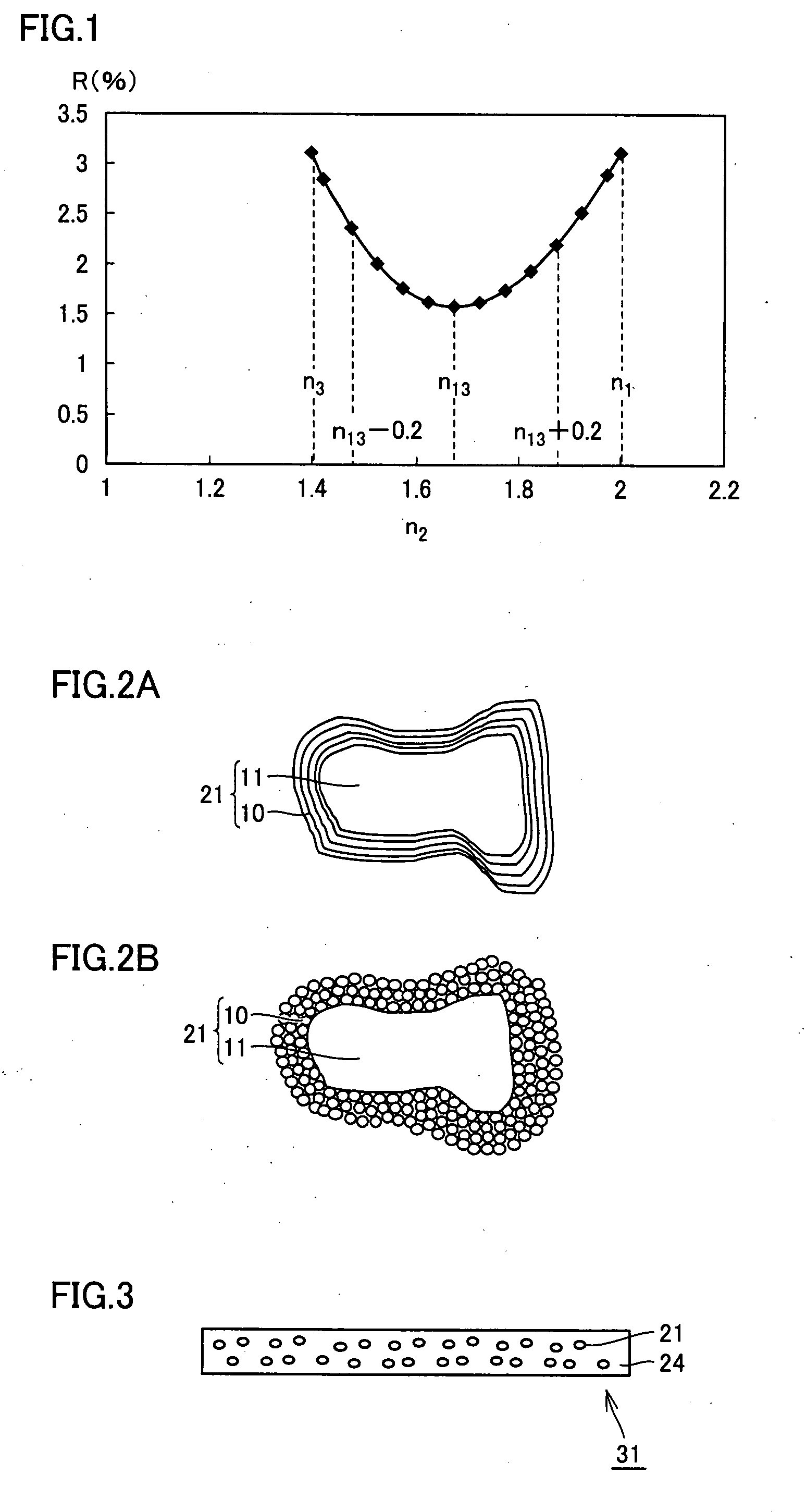
[0096]As shown in FIG. 2A, coating 10 was initially formed by successively attaching fine particles of yttrium oxide (refractive index: 1.87), fine particles of magnesium oxide (refractive index: 1.74), fine particles of aluminum oxide (refractive index: 1.63), and fine particles of silicon dioxide (refractive index: 1.5) to blue phosphor particle 11 having a indefinite shape and made of Ce-activated α sialon (compositional formula: Ca0.25Ce0.25(Si, Al)12(O, N)16, refractive index: 2.0) by a sol-gel method, so that blue phosphor 21 was fabricated. A thickness of each of the layers made of the fine particles was 30-90 nm, and a thickness of the multilayer coating was 0.3 μm.

[0097]Next, a wavelength conversion member 31 shown in FIG. 3 was fabricated as follows. Blue phosphors 21 were added to a silicone resin raw material in a liquid state and uniformly mixed. The material was then formed into a sheet having a thickness of 0.5 mm, heated at 120° C. for 60 ...

example 2

Light-Emitting Device

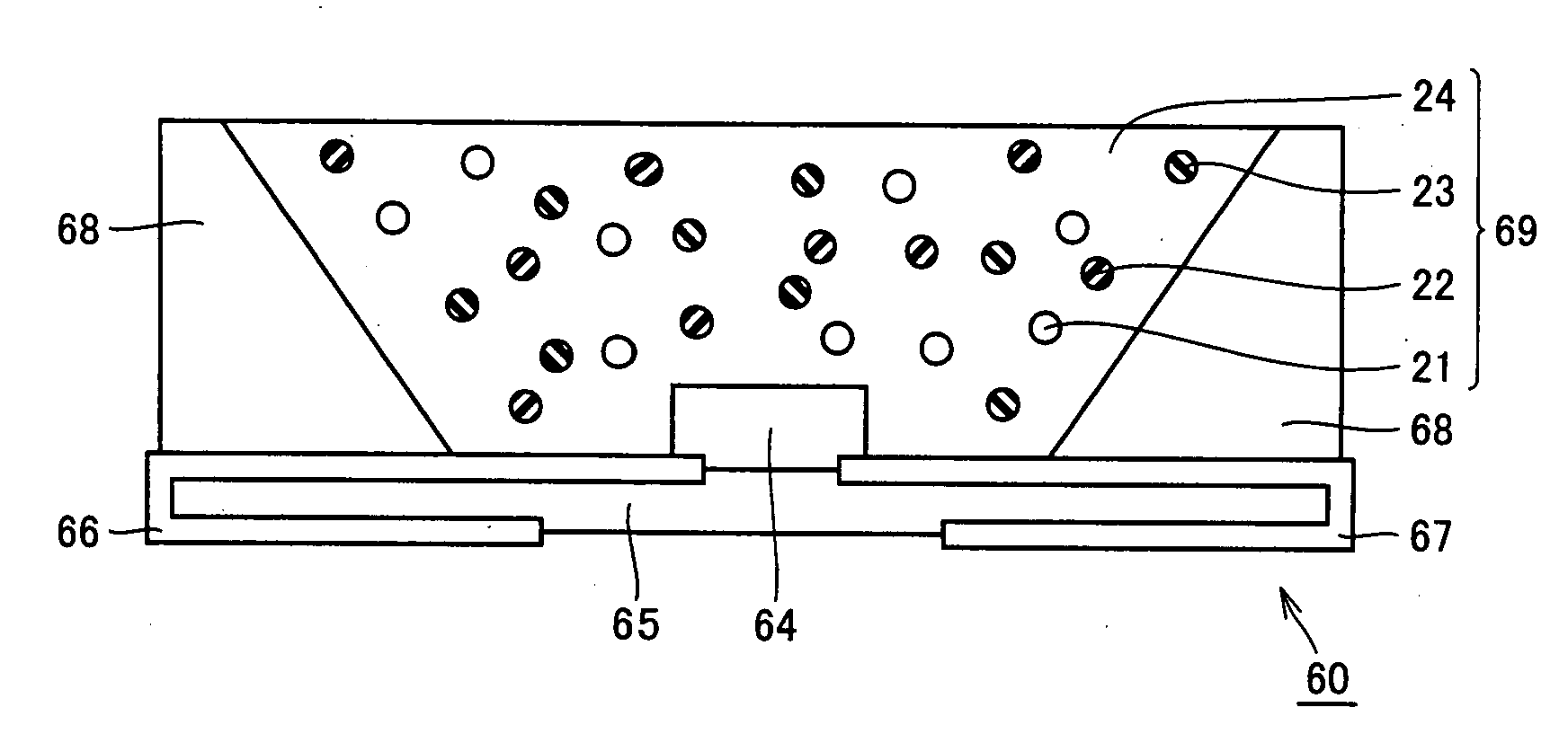
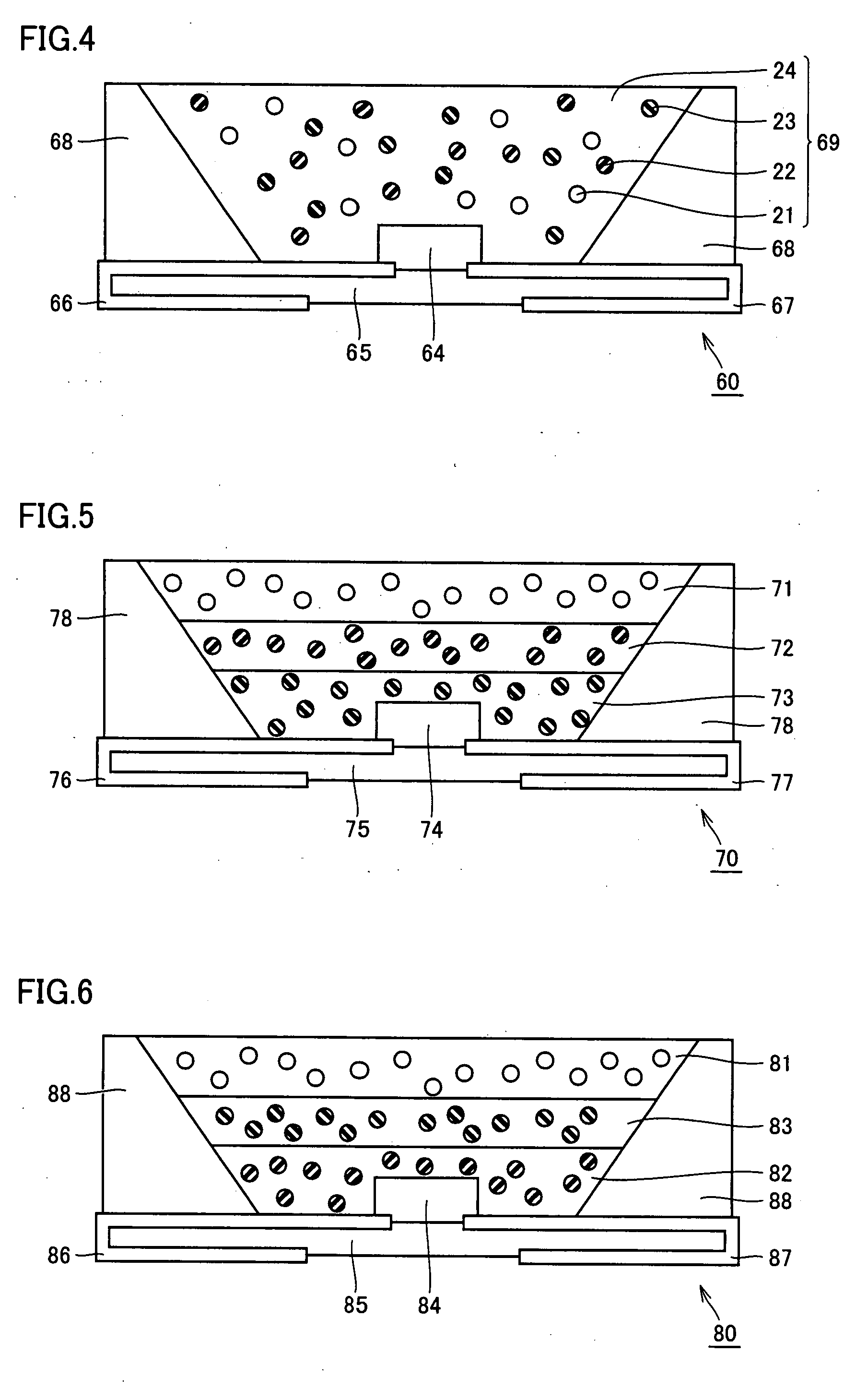
[0099]In FIG. 4, light-emitting device 60 was fabricated of base body 65, electrodes 66, 67 formed at the surface of the base body, semiconductor light-emitting element 64 electrically connected to electrodes 66, 67, mirror 68, and wavelength conversion member 69 sealing semiconductor light-emitting element 64 and converting light emitted from semiconductor light-emitting element 64 into fluorescence. Assume that wavelength conversion member 69 was made of silicone resin (refractive index: 1.4) that was to serve as medium 24, and blue phosphors 21, green phosphors 22, and red phosphors 23 dispersed in medium 24. Here, as to blue phosphors 21, green phosphors 22, and red phosphors 23, there were used blue phosphor particles made of Ce-activated α sialon, green phosphor particles made of Eu-activated β sialon, and red phosphor particles made of Eu-activated CaAlSiN3, respectively, each phosphor particles having a coating formed thereat by a method similar to that ...

example 3

Light-Emitting Device

[0104]In FIG. 5, light-emitting device 70 was fabricated of base body 75, electrodes 76, 77 formed at a surface of the base body, semiconductor light-emitting element 74 electrically connected to electrodes 76, 77, mirror 78, red phosphor layer 73, green phosphor layer 72, and blue phosphor layer 71. Note that a laminate of three types of the phosphor layers was referred to as a wavelength conversion member.

[0105]For semiconductor light-emitting element 74, there was used an LED made of a GaN-based semiconductor having an emission peak wavelength of 405 nm.

[0106]Red phosphor layer 73, green phosphor layer 72, and blue phosphor layer 71 were stacked in this order from a side near semiconductor light-emitting element 74.

[0107]For the blue phosphors dispersed in blue phosphor layer 71, there were used phosphor particles made of Ce-activated a sialon and each provided with a coating made of a magnesium oxide. For the green phosphors dispersed in green phosphor layer...


PUM


Abstract

There are provided a wavelength conversion member including phosphors made of phosphor particles which are made of an oxynitride and/or a nitride and have a refractive index n1, and a coating which coats each of the phosphor particles and has a refractive index n2, and a medium having the phosphors dispersed therein and having a refractive index n3, the refractive index n2 of the coating being a value between n3 and n1, and a light-emitting device having the wavelength conversion member incorporated therein. It is preferable in the present invention that the coating is formed of a plurality of layers, and has its refractive index varying in a stepwise manner in a direction from a surface of each of the phosphor particles to an interface with the medium.

Description

[0001]This nonprovisional application is based on Japanese Patent Application No. 2006-155098 filed with the Japan Patent Office on Jun. 2, 2006, the entire contents of which are hereby incorporated by reference.BACKGROUND OF THE INVENTION[0002]1. Field of the Invention[0003]The present invention relates to a wavelength conversion member that contains phosphors made of phosphor particles each coated with a coating, and a light-emitting device having the phosphors and a semiconductor light-emitting element such as an LED or a semiconductor laser combined therein.[0004]2. Description of the Background Art[0005]A light-emitting device that converts light emitted from a semiconductor light-emitting element such as a light-emitting diode (LED), by means of phosphors, has a small size, and less power consumption than a light bulb. Accordingly, the light-emitting device has been put into practical use to serve as a light source for various types of display devices or illuminating devices. ...

Claims


Application Information

Patent Timeline
IPC IPC(8): H01J1/62H01J63/04H01L33/32H01L33/50H01L33/54H01L33/56
CPCC09K11/0883C09K11/7721H05B33/14H01L33/504H01L33/502C09K11/77218
Inventor HARADA, MASAMICHI
Owner XIAMEN SANAN OPTOELECTRONICS CO LTD
Why Eureka
Try Eureka