Co-extrusion method of fabricating electrode structures in honeycomb substrates and ultracapacitor formed thereby

Inactive Publication Date: 2007-12-06
CORNING INC
View PDF10 Cites 22 Cited by
  • Summary
  • Abstract
  • Description
  • Claims
  • Application Information

AI Technical Summary

Benefits of technology

[0014]The method is particularly adapted to forming an ultracapacitor having a high energy storage capacity per unit volume and a relatively low weight. The high processing speeds made possible by the inventive method and the use of low-cost materials advantageously result in a low-cost energy storage device. When the honeycomb substrate is formed from a dielectric ceramic material, the resulting structure is more robust than ultracapacitors utilizing a carbonaceous honeycomb substrate, and hence is less prone to breakage or manufacturing faults that can lead to power leakage during use. The co-extruded current collectors and electrode paste deposited within the channels of the dielectric ceramic substrate prov

Problems solved by technology

Unfortunately, such a simplistic, two-electrode carbon-based design does not yield efficient electrical power.
While the power output may be increased by shortening the distance between the current collectors and the particulate carbon, the resulting lower volume of electrodes would of course reduce the available electrode area and hence the capacitance.
Unfortunately, such honeycomb-type ultracapacitors have not yet realized their full potential in providing a low-cost, high energy storage device.
It has been proven very difficult to install the rod-like, carbon electrode structures within the channels of the ceramic substrate.
No practical and time-efficient method has yet been found to produce such rod-like electrode structures and to insert the hundreds or thousands required into the small, individual openings of the honeycomb channels.
While extrusion techniques

Method used


Image

  • Co-extrusion method of fabricating electrode structures in honeycomb substrates and ultracapacitor formed thereby
  • Co-extrusion method of fabricating electrode structures in honeycomb substrates and ultracapacitor formed thereby
  • Co-extrusion method of fabricating electrode structures in honeycomb substrates and ultracapacitor formed thereby

Examples


Example

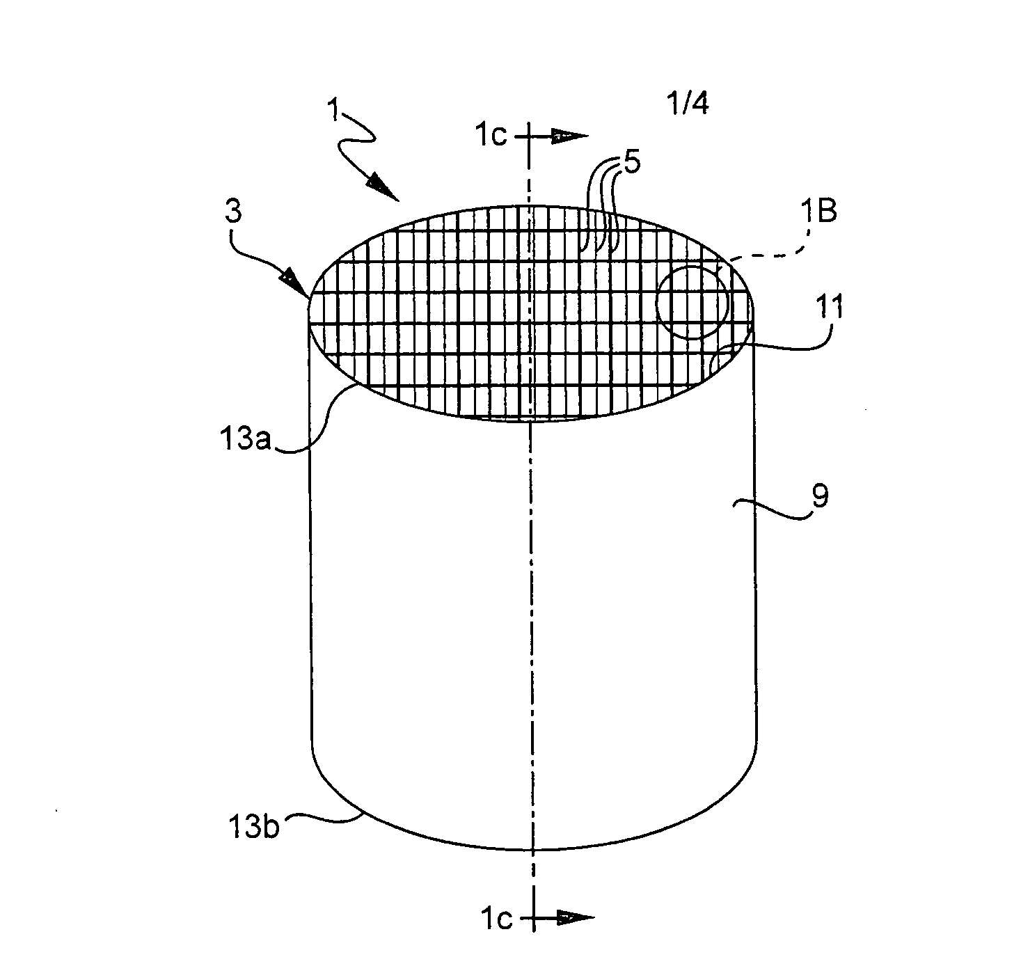
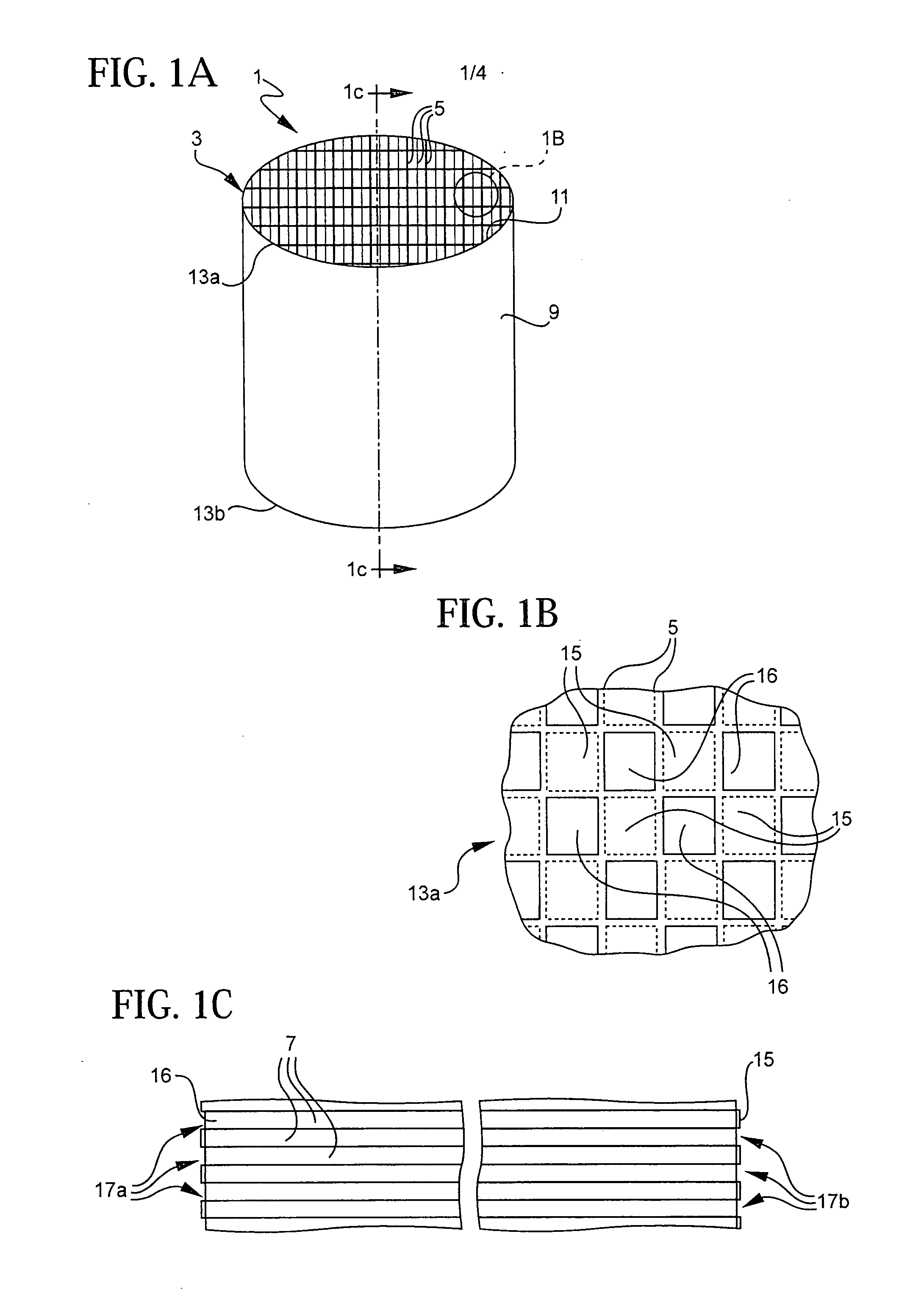
[0023]With reference to FIGS. 1A-1C, the invention is preferably applied to ceramic honeycomb substrates 1 of the type used as diesel particulate filters. Such substrates 1 include a network 3 of web walls 5 which define a plurality of elongated channels 7. While the channels 7 are illustrated as having a square cross-section in FIG. 1B, they may just as easily be hexagonal or some other polygonal shape. The web walls 5 forming the channels 7 are typically between 2.0 and 5.0 mils thick, and the density of the channels 7 may be between 300 and 2,000 channels per square inch. The ceramic substrate 1 further includes an outer skin 9 which is typically cylindrical in shape, and having a thickness of approximately three times that of the web walls 5. The network 3 of web walls 5 is integrally connected to the inner surface 11 of the outer skin 9. The honeycomb substrate 1 has generally planar opposing ends 13a, 13b as shown.

[0024]With particular reference to FIGS. 1B and 1C, the honeyco...


PUM

PropertyMeasurementUnit
Diameteraaaaaaaaaa
Diameteraaaaaaaaaa
Surface areaaaaaaaaaaa

Abstract

A method for fabricating electrode structures within a honeycomb substrate having a plurality of elongated channels is provided that is particularly adaptable for producing an ultracapacitor. In this method, the nozzle of a co-extrusion device simultaneously feeds a current collector along a central axis of one of the channels while simultaneously injecting a paste containing an electrode material so that the interior of the channel becomes completely filled with electrode paste at the same rate that the current collector is fed. Such co-extrusion as performed simultaneously at both sides of the ceramic substrate to rapidly form electrode structures within substantially all the channels of the substrate. The resulting ultracapacitor is capable of storing large amounts of electrical energy per unit volume in a structure which is relatively quick and easy to manufacture.

Description

[0001]This application claims the benefit of U.S. Provisional Application No. 60 / 809,582, filed May 30, 2006, entitled “Co-Extrusion Method of Fabricating Electrode Structures in Honeycomb Substrates and Ultracapacitor Formed Thereby.”FIELD OF THE INVENTION[0002]This invention generally relates to ultracapacitor energy storage devices, and is particularly concerned with a method for forming electrode structures within the channels of a honeycomb substrate, and the ultracapacitor formed thereby.BACKGROUND OF THE INVENTION[0003]Electric double layered capacitors (EDLC), commonly known as ultracapacitors, are known in the prior art. Such devices are capable of storing larger amounts of electrical energy per unit volume than the traditional capacitors, generating much higher power in a short instant than many types of chemical batteries, and may be charged and discharged a large number of times with virtually no energy losses due to chemical reaction. Ultracapacitors having capacitances...

Claims


Application Information

Patent Timeline
IPC IPC(8): H01G9/155
CPCH01G11/28Y10T29/10H01G11/70Y10T29/49204Y10T29/417H01G11/38H01G11/86H01G11/26Y10T29/49002H01G9/155Y02T10/7022H01G9/016Y02E60/13Y02T10/70H01G11/74
Inventor MILLER, WILLIAM JAMESSHENG, HUAN-HUNG
Owner CORNING INC
Why Eureka
Try Eureka