Devices, systems and methods for determining parameters of one or more phases of an injection procedure

a technology of parameters and injection procedures, applied in the field of devices, systems and methods for delivering pharmaceutical fluids to patients, can solve the problems of different results in image contrast and quality, the manpower in which such parameters are to be determined for a specific procedure for a specific patient is not well developed, and the injection profile computed by inverse solution of the pk model is not readily realizable by most ct power injectors without major modification

Active Publication Date: 2007-12-06
BAYER HEALTHCARE LLC
View PDF70 Cites 65 Cited by
  • Summary
  • Abstract
  • Description
  • Claims
  • Application Information

AI Technical Summary

Benefits of technology

[0022] The parameter generator can, for example, determine parameters for at least one phase at least in part on the basis of a test injection. In one embodiment, the parameter generator determines parameters for at least one phase (for example, an admixture phase) at least in part on the basis of time to peak enhancement determined in a test injection. For example, a ratio of contrast enhancing fluid to non-contrast enhancing fluid in an admixture phase can be determined by the parameter generator on the basis of time to peak enhancement. In one embodiment, a longer time to peak enhancement results in a higher ratio of contrast enhancing fluid to non-contrast enhancing fluid.

Problems solved by technology

However, the manner in which such parameters are to be determined for a specific procedure for a specific patient are not well developed.
Although using standard, fixed or predetermined protocols (whether uniphasic, biphasic or multiphasic) for delivery simplifies the procedure, providing the same amount of contrast media to different patients under the same protocol can produce very different results in image contrast and quality.
However, the injection profiles computed by inverse solution of the PK model are profiles not readily realizable by most CT power injectors without major modification.
Uniphasic administration of contrast agent (typically, 100 to 150 mL of contrast at one flow rate) results in a non-uniform enhancement curve.
A fundamental difficulty with controlling the presentation of CT contrast agent is that hyperosmolar drug diffuses quickly from the central blood compartment.
Because the method of Fleischmann et. al. computes input signals that are not realizable in reality as a result of injection system limitations (for example, flow rate limitations), one must truncate and approximate the computed continuous time signal.
In addition to potential hazards to the patient (for example, vessel damage) and potential degradation of the diagnostic and / or therapeutic utility of the injection fluid, excessive pressure can lead to equipment failure.
If the injector causes pressure in the fluid path to rise above the burst strength of a disposable fluid path element, the fluid path element will fail.
This technique has inherent accuracy problems, as there are many variables between the parameter being measured (motor current) and the parameter of interest (fluid pressure).
The inaccuracies inherent in using motor current to derive pressure result in a compliant system, and the operation of the servo in that state is oscillatory.
Pressures in excess of desirable limits can occur, resulting in potentially hazardous operation of the injector.
In addition to problems of control with current injector systems, many such systems lack convenience and flexibility in the manner in which the injector systems must be operated.
For example, the power delivered to the drive mechanism can be limited in a manner so that the pressure hazard limit or upper hazard level is not reached.
In that regard, a pressure limit below the pressure hazard limit can be set such that power delivered to the drive mechanism is limited when the lower pressure limit is reached.

Method used


Image

  • Devices, systems and methods for determining parameters of one or more phases of an injection procedure
  • Devices, systems and methods for determining parameters of one or more phases of an injection procedure
  • Devices, systems and methods for determining parameters of one or more phases of an injection procedure

Examples


Embodiment Construction

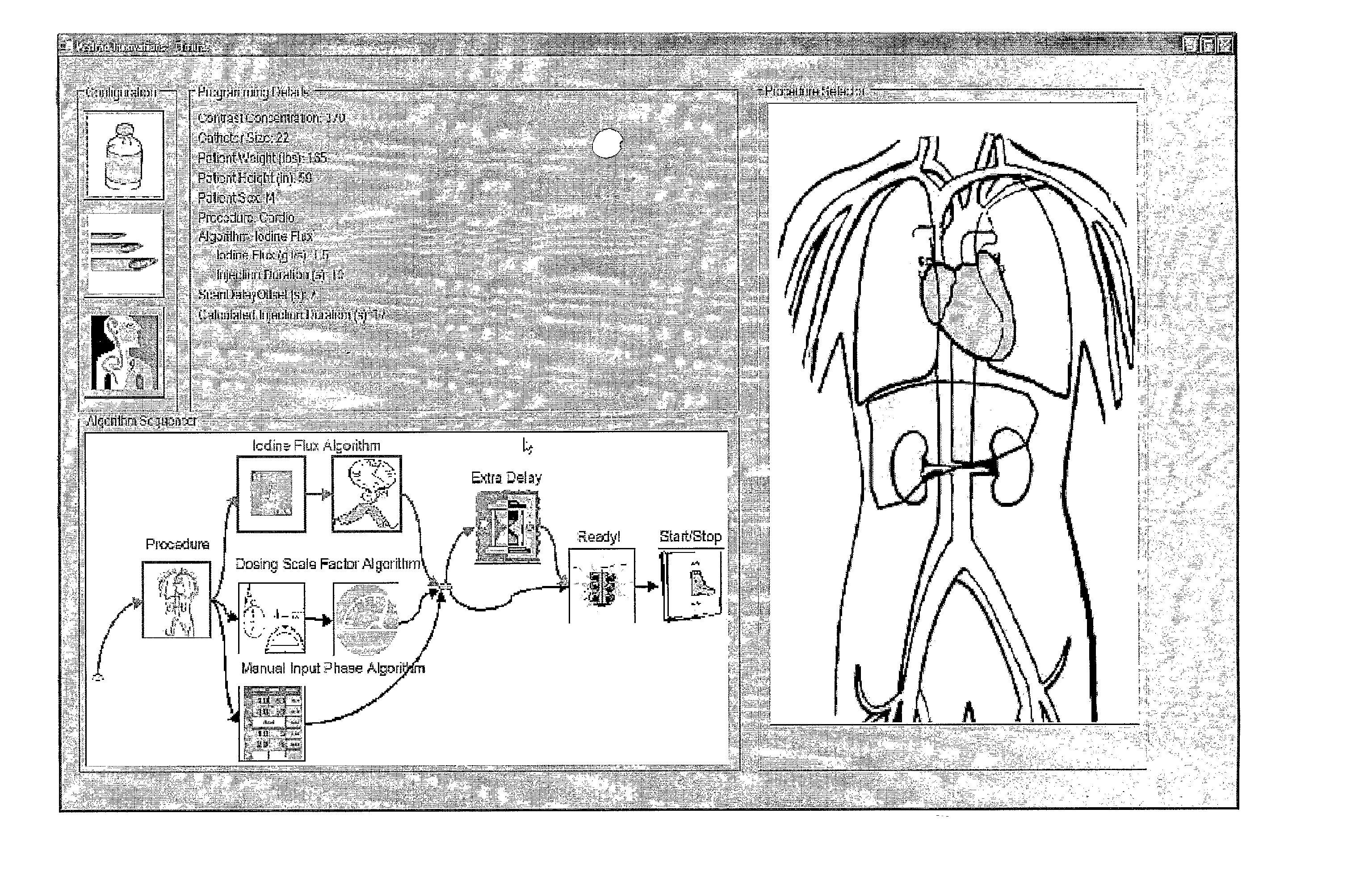
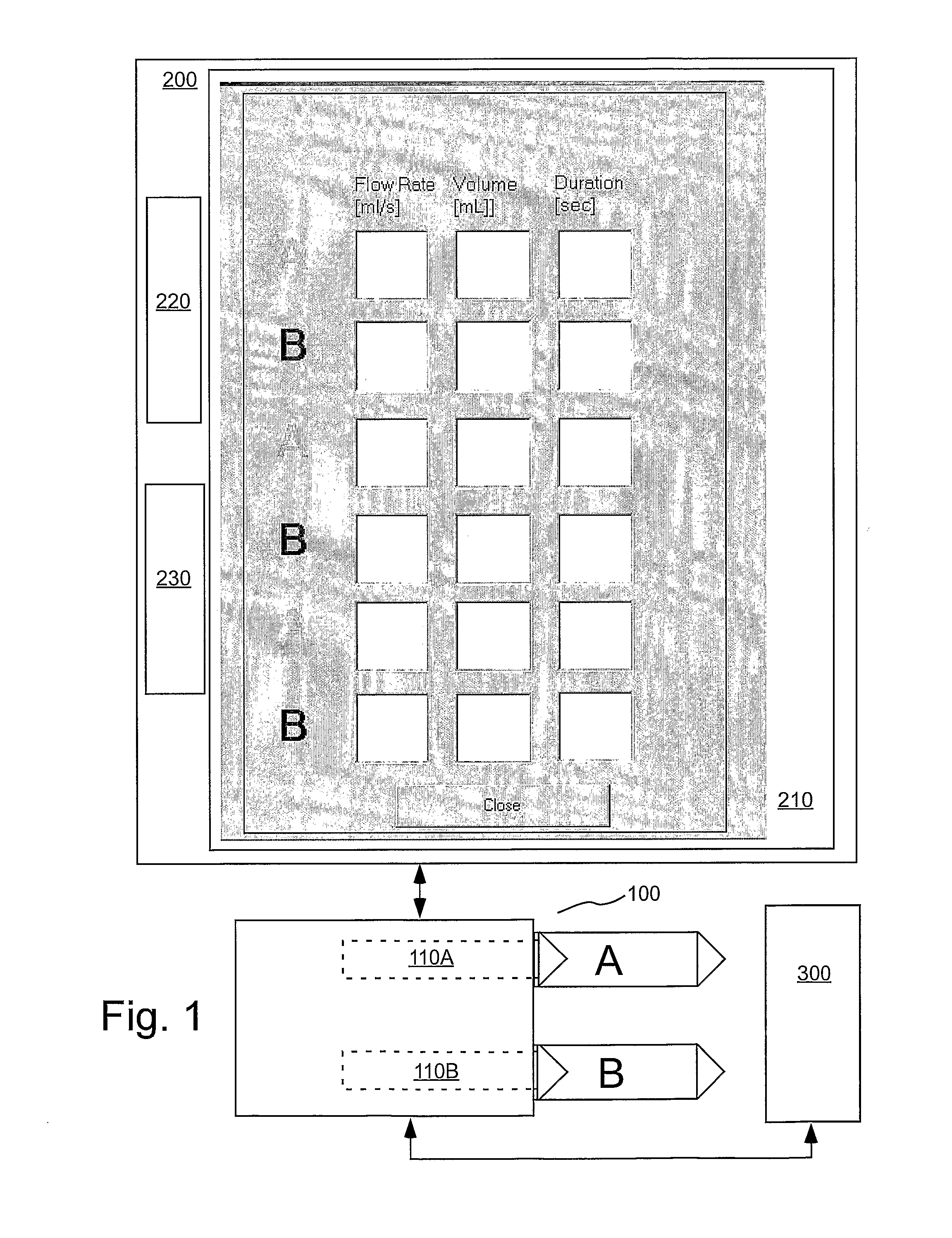
[0067] In several embodiments of the present invention, an injection system (such as a dual syringe injector system 100 as illustrated in FIG. 1 and as, for example, disclosed in U.S. Pat. No. 6,643,537 and Published U.S. Patent Application Publication No. 2004-0064041) for use with the present invention includes two fluid delivery sources (sometimes referred to as source “A” and source “B” herein; such as syringes) that are operable to introduce a first fluid and / or a second fluid (for example, contrast medium, saline etc.) to the patient independently (for example, simultaneously, simultaneously in different volumetric flow proportion to each other, or sequentially or subsequent to each other (that is, A then B, or B then A)). In the embodiment of FIG. 1, source A is in operative connection with a pressurizing mechanism such as a drive member 110A, and source B is in operative connection with a pressurizing mechanism such as a drive member 110B. The injection system includes a con...


PUM


Abstract

A fluid injection apparatus includes at least one pressurizing mechanism and at least a first fluid container (for example, a syringe or a bulk container) operably associated with the at least one pressurizing mechanism. The first fluid container is adapted to contain a first fluid to be injected. The fluid injection apparatus also includes a controller operably associated with the at least one pressurizing mechanism. The controller includes a programming system to allow programming of an injection protocol including, for example, a plurality of phases. At least one parameter generator is provided to determine parameters of at least one of the plurality of phases of the protocol based at least in part upon a type of the injection procedure.

Description

CROSS-REFERENCE TO RELATED APPLICATION [0001] This application claims benefit of U.S. Provisional Patent Application Ser. No. 60 / 631,015, filed Nov. 24, 2005, the disclosure of which is incorporated herein by reference.BACKGROUND OF THE INVENTION [0002] The present invention is relates to devices, systems and methods for fluid delivery, and, particularly, to devices, systems and methods for delivery of a pharmaceutical fluid to a patient, and, especially for delivery of a contrast medium to a patient during a medical injection procedure. [0003] In many procedures, the administration of contrast medium (with an electronic power injector) for radiological exams starts with the clinician filling an empty, disposable syringe with a certain volume of contrast agent pharmaceutical. In other procedures, a syringe pre-filled with contrast agent is used. The clinician then determines a volumetric flow-rate and a volume of contrast to be administered to the patient to enable a diagnostic imag...

Claims


Application Information

Patent Timeline
Patent Type & Authority Applications(United States)
IPC IPC(8): A61M37/00
CPCA61M5/14546A61M5/16854A61B6/507G06F19/3406A61M2005/14208G16H40/63A61M5/007A61M2205/3334A61M2205/50A61M2230/04
Inventor KALAFUT, JOHN F.MISHLER, DAVID A.
Owner BAYER HEALTHCARE LLC
Why Eureka
Try Eureka