Device, System and Method for Cutting, Cleaving or Separating a Substrate Material

a substrate material and cutting technology, applied in glass making apparatus, manufacturing tools, welding/soldering/cutting articles, etc., can solve the problems of slow process speed, poor understanding of laser scribing mechanism, and inability to meet the needs of many applications, and achieve fast, reliable laser scribing.

Inactive Publication Date: 2007-12-13
APPL PHOTONICS INC +1
View PDF10 Cites 20 Cited by
  • Summary
  • Abstract
  • Description
  • Claims
  • Application Information

AI Technical Summary

Benefits of technology

[0026] To overcome these and several other disadvantages, the present invention uses several innovative techniques that provide f

Problems solved by technology

Despite prolific activity, this technique has not yet become commercially viable for many applications.
The primary reasons for this situation are slow process speeds, use of complicated laser modes, poor understanding of laser scribing mechanisms, and time consuming, archaic two-step processes (e.g. scribe and break) which generate particulate and microcracks and thus counteract a primary advantage of laser separation.
This is especially true if the substrate thickness is greater than 0.4 mm and thus the residual tensile forces in the substrate are not sufficient to separate the substrate.
Other techniques use dual break beams that are too wide, usually >8 mm causing thermal shock on the perimeter of the intended cut.
This leads to weakening and/or uncontrolled cracking of the glass.
Also, there are many cases when the separation has to occur within a limited path width due to the presence of electronic devices or coatings/layers on either side of the cut.
However, even with optimized quenching, proper initial boundary conditions are required to successfully achieve laser scribing.
However, the residual tensile forces are not as controllable as the new methods described herein.
For thicker material, the residual tensile forces from the laser scribing operation are not usually sufficient to fully separate the material.
In other cases, the tensile forces are so great that the material separates in an uncontrollable manner and can move well ahead of the quenching region.
This results in a compromise in straightness since the separation dynamics are controlled by thermal gradients alone which are, by nature, asymmetric.
However, these techniques lead to irregular cuts due to inherent asymmetries.
The edge of a substrate is much weaker than the bulk of the material thus making it susceptible to uncontrolled cracking after introducing thermal shock.
In addition, there are often microcracks present along the edge of a material due mechanical processes such as edge grinding which need to be considered as well.
In addition, as edge treatment techniques improve, it

Method used


Image

  • Device, System and Method for Cutting, Cleaving or Separating a Substrate Material
  • Device, System and Method for Cutting, Cleaving or Separating a Substrate Material
  • Device, System and Method for Cutting, Cleaving or Separating a Substrate Material

Examples


Embodiment Construction

[0079] Herein below, the embodiments of the present invention are described with reference to the accompanying drawings.

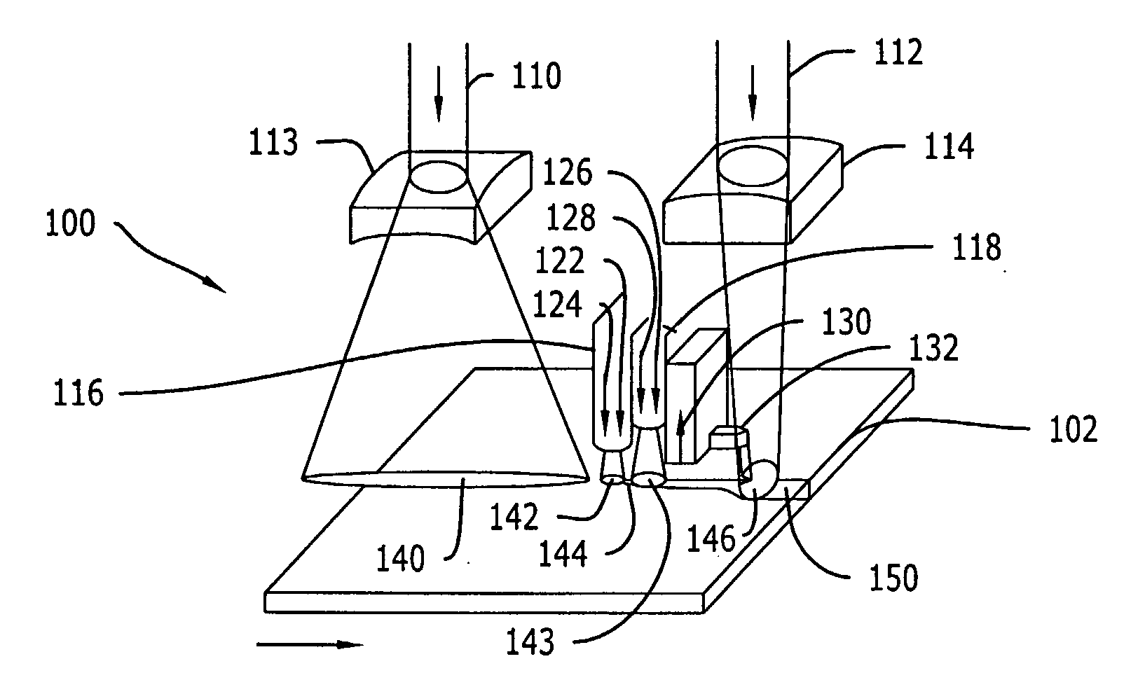
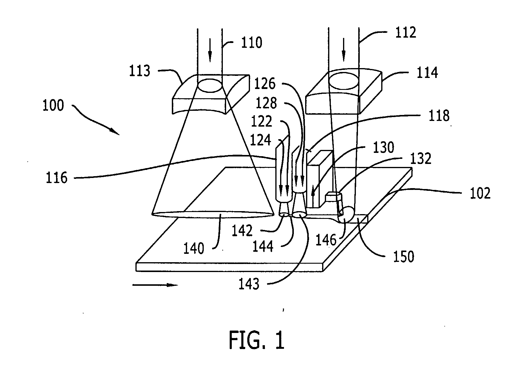
[0080]FIG. 1 is a schematic overview of an apparatus for separating nonmetallic materials according to the present invention. The separating apparatus generally indicated by reference numeral 100 for separating a nonmetallic material 102 includes two laser beams 110 and 112 and at least two quenching nozzles 116 and 118.

[0081] The nonmetallic substrate 102 is moved along relative to the separating apparatus 100 in the direction shown by the arrow below the nonmetallic substrate 102, such as glass. The laser beam 110 passes through a lens 113 and focuses to a scribe laser beam heating region 140. The two quenching nozzles 116 and 118 are shown schematically as forming quenching zones 142 and 143, respectively on the nonmetallic substrate 102. Between the quenching zones 142 and 143 is a propagated scribe line 144. The laser beam 112 passes through a lens 114 and f...


PUM

PropertyMeasurementUnit
Lengthaaaaaaaaaa
Angleaaaaaaaaaa
Poweraaaaaaaaaa

Abstract

An apparatus and method for separating a nonmetallic substrate is disclosed as including a first beam; a first quenching device positioned so that a coolant stream may be applied to the substrate at or immediately adjacent to the trailing end of the first spot; a second beam; and a second quenching device positioned between the first quenching device and the second beam. At least one of an angle at which the first scribe beam impinges on the substrate and an energy intensity of the first scribe beam impinging on the substrate are adjusted to obtain right angle separation. A crack sensor and controller can also be provided for measuring a position of the cut line, comparing the position with a reference position and adjusting the power intensity of the second beam based on the comparison of the position of the cut line with the reference position.

Description

CROSS REFERENCE TO RELATED APPLICATIONS [0001] This application claims the benefit of U.S. Provisional Application No. 60 / 581,856 filed Jun. 21, 2004 and U.S. Provisional Application No. 60 / 582,195 filed Jun. 22, 2004, and hereby incorporates these applications herein by reference.BACKGROUND OF THE INVENTION [0002] 1. Field of the Invention [0003] The present invention generally concerns cutting and separating technology. More particularly, the present invention involves a device, system and method for cutting, cleaving, and / or separating nonmetallic or brittle materials using lasers. [0004] 2. Discussion of the Related Art [0005] The technique of propagation of a microcrack in a brittle material using a laser has been known for more than three decades. U.S. Pat. No. 3,610,871 issued to Lumley in 1971, is an early well known disclosure. Despite prolific activity, this technique has not yet become commercially viable for many applications. The primary reasons for this situation are s...

Claims


Application Information

Patent Timeline
IPC IPC(8): B29C37/00
CPCB23K26/03C03B33/093B23K26/034B23K26/038B23K26/04B23K26/0604B23K26/073B23K26/083B23K26/0869B23K26/1405B23K26/1417B23K26/4075B23K26/421C03B33/03C03B33/07B23K26/032B23K26/0344B23K26/142B23K26/146B23K26/60B23K26/40B23K2103/50
Inventor HOEKSTRA, BRIAN
Owner APPL PHOTONICS INC
Why Eureka
Try Eureka