Transparent Film And Optical Compensatory Film, Polarizing Plate And Liquid-Crystal Display Device Employing It

a liquid crystal display device and transparent film technology, applied in the direction of polarizing elements, instruments, transportation and packaging, etc., can solve the problems of axial shifting of biaxial films, difficult to completely optically compensate liquid crystal cells with no problems, and difficult to achieve the effect of preventing light leakage, improving viewing angle dependency of contrast, and contributing to optical compensation

Active Publication Date: 2007-12-13
FUJIFILM CORP
View PDF7 Cites 25 Cited by
  • Summary
  • Abstract
  • Description
  • Claims
  • Application Information

AI Technical Summary

Benefits of technology

[0035] In the invention, a transparent film having a wavelength dispersibility characterized in that the positivity/negativity of Rth thereof is reversed at a particular wavelength is used to improve the viewing angle dependency of the contrast and the color change in a liquid-crystal cell, especially in an IPS-mode liquid-crystal cell. The transparent film may be employed in a liquid-crystal display device, as a member such as a protective film for the polarizing plate therein or as an optical compensatory film the

Problems solved by technology

However, the TN mode has such viewing-angle characteristics that it has excellent display characteristics when seen in the front direction thereof but its display characteristics worsen when seen in the oblique direction in that its contrast lowers and it causes grayscale inversion which means brightness inversion in grayscale state, and improving it is greatly desired.
Accordingly, minor light leakage in the diagonal oblique incident direction in a black state, which, however, has not heretofore been considered problematic in those display modes, has become considered as a problem for the reasons of display quality depression.
However, many of the proposed systems are for canceling the birefringence anisotropy of the liquid crystal in a liquid-crystal cell to thereby improve the viewing angle characteristics of display devices, and are therefore still problematic in that they could not solve the problem of light leakage to be caused by the shifting of

Method used


Image

  • Transparent Film And Optical Compensatory Film, Polarizing Plate And Liquid-Crystal Display Device Employing It
  • Transparent Film And Optical Compensatory Film, Polarizing Plate And Liquid-Crystal Display Device Employing It
  • Transparent Film And Optical Compensatory Film, Polarizing Plate And Liquid-Crystal Display Device Employing It

Examples


example 1-1

Formation of Transparent Film

[0301] A polycarbonate film “Panlite C1400” (by Teijin Chemical), a thermoplastic norbornene resin (JSR's Arton) and Zeonoa (by Nippon Zeon) were dissolved in methylene chloride to prepare a solution. A compound having the ability to reduce optical anisotropy (Re (λ) and Rth (λ)), shown in Table 1-1, was added to the solution in a predetermined amount relative to the polymer solid content of the solution, and the resulting solution was cast to form a transparent film having a thickness of 40 m (001 to 006). Regarding the optical properties thereof, it is understood that the positivity / negativity of Rth of the transparent films of the invention, 002, 004 and 006 is reversed at 400 nm and 700 nm.

TABLE 1-1Optical Anisotropy-Reducing AgentAmount Added %FilmReRthRthRthPolymer(polymer solidThickness(630)(630)(400)(700)Sample NumberMaterialCompoundcontent 100)μmnmnmnmnmCom. Ex. *1001PanliteNo—401221727C1400In. *2002PanliteA-195%40613−120C1400Com. Ex. *1003Ar...

example 1-2

Formation of Transparent Film

(Preparation of Cellulose Acylate Solution)

[0303] Using various cellulose acylates as in Table 1-2, the following composition was put into a mixing tank and stirred to dissolve the components, thereby preparing a cellulose acylate solution.

[0304] (Composition of Cellulose Acylate Solution)

Cellulose acylate100.0mas. pts.Methylene chloride (first solvent)402.0mas. pts.Methanol (second solvent)60.0mas. pts.

(Preparation of Mat Agent Solution)

[0305] 20 parts by mass of silica particles having a mean particle size of 16 nm (Aerosil R972 by Nippon Aerosil) and 80 parts by weight of methanol were well stirred and mixed for 30 minutes to prepare a dispersion of silica particles. The dispersion was put into a disperser along with the following composition thereinto, and further stirred therein for 30 minutes or more to dissolve the components, thereby preparing a mat agent solution.

[0306] (Composition of Mat Agent Solution)

Dispersion of silica particles...

example 1-3

Evaluation of Transparent Film Fitted in Liquid-Crystal Display Device

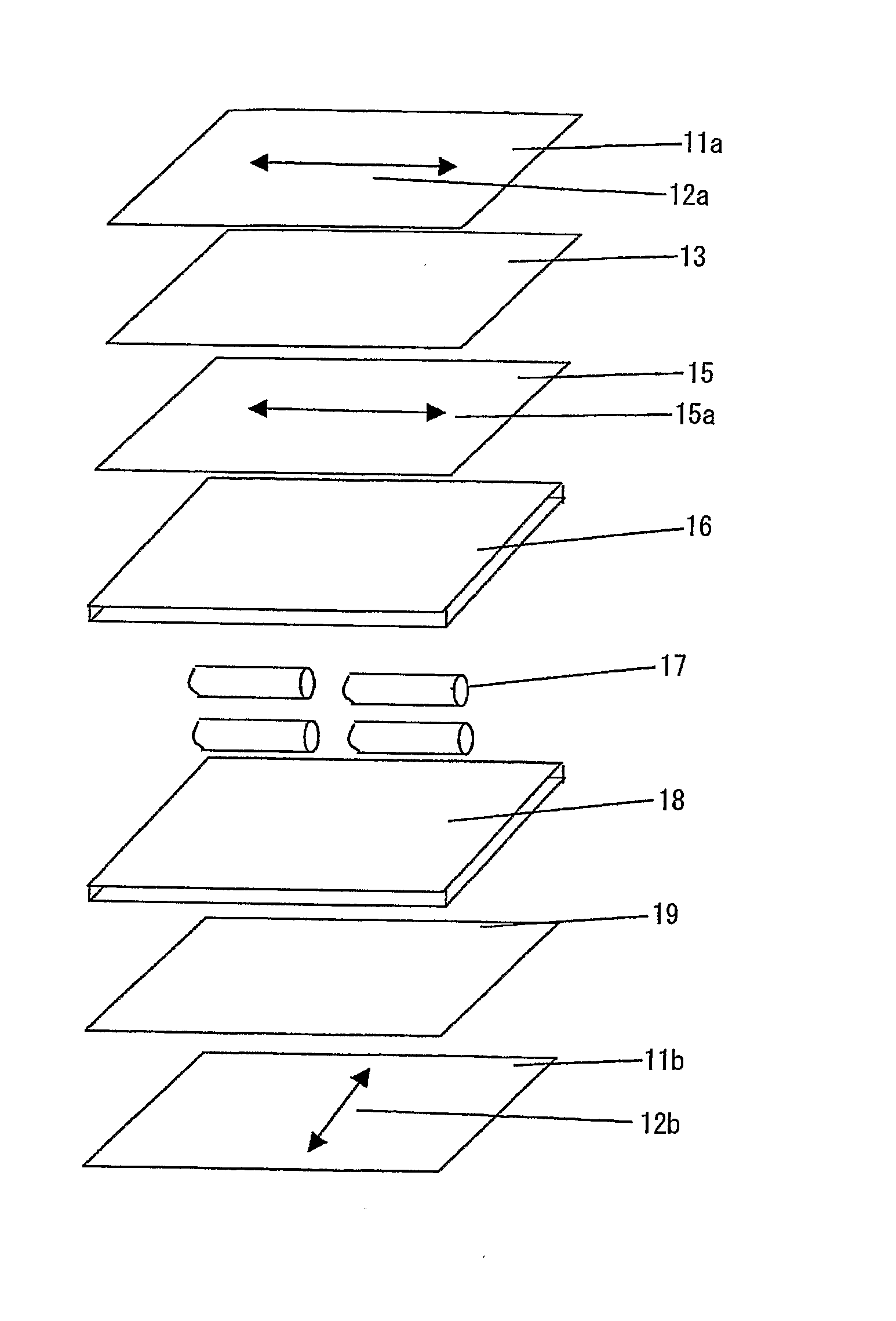
[0312] An IPS-mode liquid-crystal display device having the constitution as in FIG. 7 was constructed. Concretely, liquid-crystal molecules 17 were put in and sealed up between a pair of substrates 16 and 18 to form a liquid crystal cell. The cell was disposed between a pair of polarizing films 11a and 11b. A transparent film 19 of the invention was disposed between the liquid-crystal cell and the lower polarizing film 11b; and a first optical compensatory film 15 and a second optical compensatory film 13 were disposed between the liquid-crystal cell and the upper polarizing film 11a. The relationship between the transmission axis 12a, 12b of the polarizing film and the slow axis 15a of the first optical compensatory film is described in each Example. In FIG. 7, the constitutive components are drawn as independent members for convenience sake. As the case may be, however, some member in this may be integrated wit...


PUM

PropertyMeasurementUnit
Percent by massaaaaaaaaaa
Thicknessaaaaaaaaaa
Lengthaaaaaaaaaa

Abstract

A novel transparent film is disclosed. Re (λ) and Rth (λ) of the film defined by the following formulae (I) and (II) satisfy the following formulae (III) and (IV):
Re (λ)=(nx−nyd,  (I)
Rth (λ)={(nx+ny)/2−nz}×d,  (II)
0≦|Re(630)|≦50,  (III)
Rth (400)×Rth (700)≦0, and 0<|Rth (700)−Rth (400)|≦150,  (IV)
wherein Re (λ) means an in-plane retardation value at a wavelength λ nm (unit: nm); Rth (λ) means a thickness-direction retardation value at a wavelength λ nm (unit: nm); nx means a refractive index in the in-plane slow-axis direction; ny means a refractive index in the in-plane fast-axis direction; nz means a refractive index in the film thickness direction; and d means a thickness of the film.

Description

TECHNICAL FIELD [0001] The present invention relates to a transparent film, and to an optical compensatory sheet, a polarizing plate and a liquid-crystal display device employing the film. BACKGROUND ART [0002] A liquid-crystal display device generally comprises a liquid-crystal cell and a polarizing plate. The polarizing plate has a protective film and a polarizing film, and this is obtained, for example, by dyeing a polarizing film formed of a polyvinyl alcohol film with iodine, stretching it and then laminating a protective film on both faces thereof. In general, a transmission liquid-crystal display device may comprise such a polarizing plate fitted to both sides of the liquid-crystal cell thereof, and may further has one or more optical compensatory film provided therein. A reflection liquid-crystal display device may generally comprise a reflector, a liquid-crystal cell, one or more optical compensatory films and a polarizing plate disposed in that order. The liquid-crystal ce...

Claims


Application Information

Patent Timeline
IPC IPC(8): G02F1/1335G02B5/30C08J5/18G02F1/13363G02F1/1339G02F1/1343
CPCC08J5/18C08J2301/12C08J2365/00G02B5/305Y10T428/105G02F1/134363G02F2001/13396G02F2203/04G02F1/133634C09K2323/035G02F1/13396G02B5/30G02F1/1335
Inventor NAKAYAMA, HAJIMESAITOH, YUKITO
Owner FUJIFILM CORP
Why Eureka
Try Eureka