
Microfluidic Device

a microfluidic device and microfluidic technology, applied in microstructural technology, biochemistry apparatus and processes, material testing goods, etc., can solve the problems of porosity and mechanical integrity of materials, high electrical fields, and inability to sustain on silicon substrates without electrical breakdown, etc., to achieve high degree of sealing and avoid fluid leakage

Inactive Publication Date: 2007-12-13
MICRONIT MICROTECHNOLOGIES BV
View PDF16 Cites 57 Cited by
  • Summary
  • Abstract
  • Description
  • Claims
  • Application Information

AI Technical Summary

Benefits of technology

[0021] It is therefore an object of the present invention to overcome at least one of the above and other drawbacks of the prior art and to provide a method of fabricating a microfluidic device with a relatively high degree of sealing in order to avoid leakage of fluid.

Problems solved by technology

A major drawback of the systems derived from the field of micro-electronics is that high electrical fields are needed to establish electro osmotic or electrophoretic principles, which generally can not be sustained on a silicon substrate without electrical breakdown.
An important issue in the fabrication of such glass devices, as well as of devices which comprise one glass substrate and one other substrate, the latter being e.g. a silicon or a polymer substrate, as well as of devices which comprise any combination of these substrate materials, is the sealing of the microfluidic capillary circuit that is formed by combining the two substrates, of which at least one contains an etched or by other means engraved channel pattern.
Some sealing methods use dispensed polymer forming liquids, such as epoxies and the such as, which are considered undesirable for fluidic chip sealing purposes for several reasons, the most important being the difficulties in dispensing a uniformly thick material layer on exact positions along the periphery of an engraved channel, the porosity and mechanical integrity of the material, and the interference of the material with e.g. organic solvents in the channel of the fluidic system during operation.
Drawback is the high electrical field that is required for the process, which in some cases will result in bonding of channel walls in unwanted locations.
A drawback of this method is that it can only be applied for bonding of a glass substrate to a metal or semiconducting substrate, which limits the use of the resulting devices to applications at low electrical fields and relatively low temperatures.
The requirement of low temperatures, generally below about 400° C., is the result of the differences in thermal expansion that exist for most combinations of glass and metal or semiconductor substrates, and which lead to unwanted deformations of the substrate sandwich after bonding during temperature cycles.
This method generally works well for electronic applications, but may lead to unwanted leakage in fluidic applications, in particular if the chip is used at high pressures, which is relevant for separation and synthetic chemistry applications.
This was described in the previously mentioned publication by Harrison et al., and has as important drawbacks the occurrence of leakage when one of the substrates contains surface topography such as metal patterns and the possible deformation of the substrates when they are pressed together in a softened or partially molten state, by which the structural integrity of the fluidic circuit contained in one or both of the substrates will be affected.
Drawback of this method is that the layer during dispension or during melting may destroy the structural integrity of the fluidic circuit, due to re-flow of the material.
Consequently, the previous methods have the disadvantages that an electric field is required for bonding, that a (partially) molten state or application of pressure is required, and / or that the method is limited to a particular choice of substrate material or film material on the substrate.
Further drawbacks of the above methods become evident from the following when sealing is required on metal patterns that are present in-between the two glass plates, between a glass plate and a silicon plate, or between two silicon plates.
As discussed by Harrison et al. in the previously mentioned publication, sealing over platinum lines that extended over one of the glass substrates showed liquid leakage even after a careful heat treatment during the thermal bonding procedure.
The prevention of leakage is crucial for fluidic microsystems, since leakage will give rise to cross-talk between adjacent fluidic conduits and leads to dead-volumes that give rise to cross-contamination of subsequent sample injections.
This known device is considered undesirable not only because of the extra photolithographic steps that are required during fabrication of the device, but even more because of the necessity of an exact dimensional match and positional alignment of the metal pattern with the etched recess.
In particular, the required recess depth uniformity and metal film thickness uniformity over the substrate area, as well as the lithographic overlay quality, is difficult to obtain with most state-of-the-art etching and deposition apparatus, and can only be achieved with very well-tuned and expensive equipment.
This is the reason why the method is frequently observed to fail in conventional fabrication environments, and leak-tight sealing is not obtained with the method.

Method used


Image

  • Microfluidic Device
  • Microfluidic Device
  • Microfluidic Device

Examples


Embodiment Construction

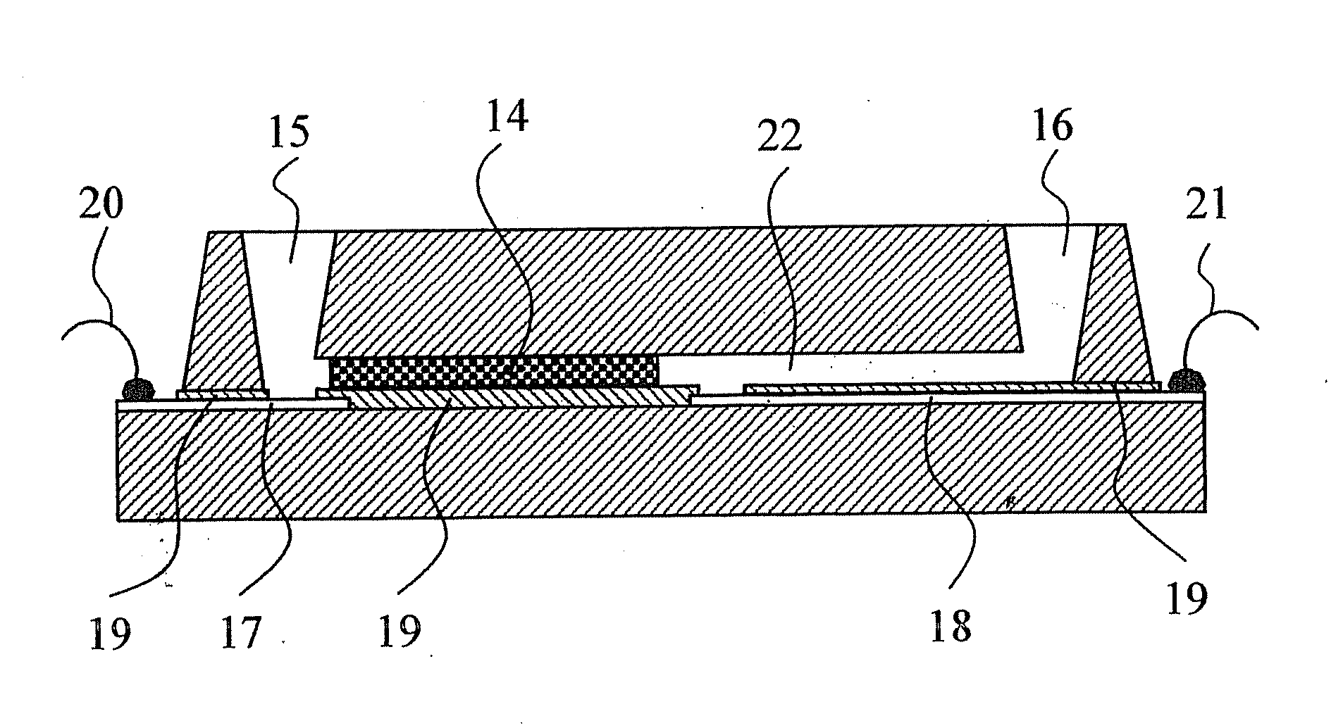
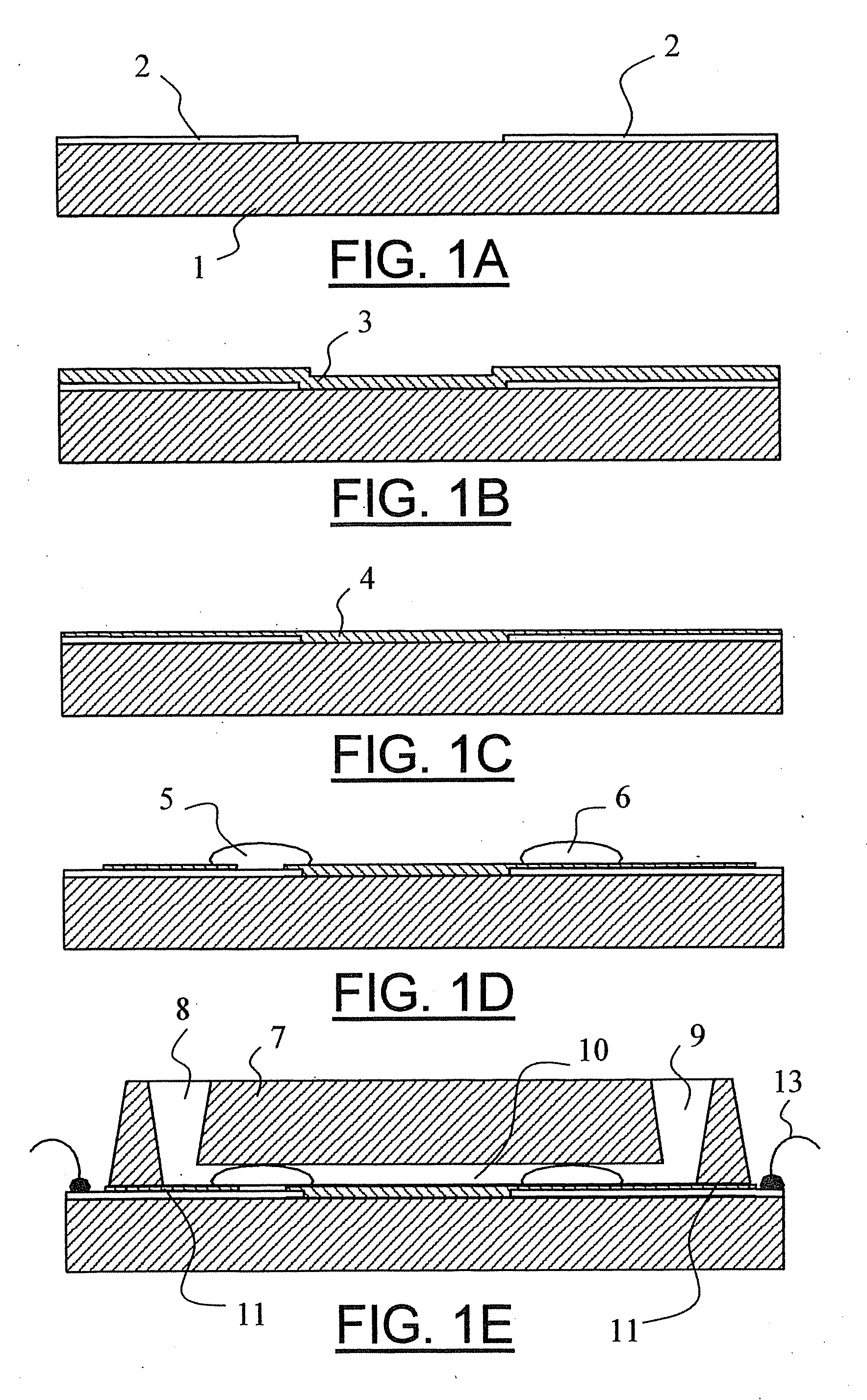
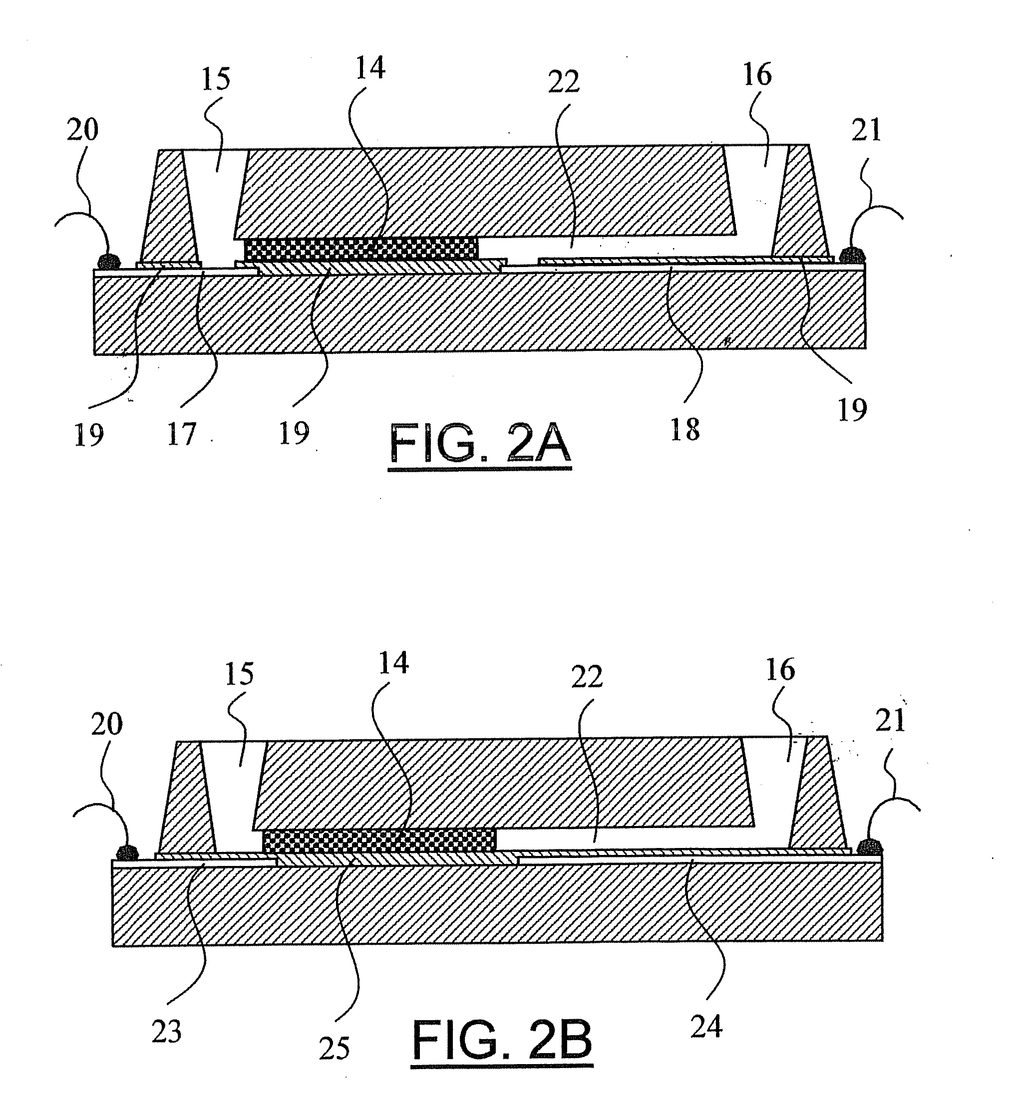
[0072]FIGS. 1A-1E describe a preferred process sequence. FIG. 1A shows a glass substrate 1 on which a thin metal pattern 2 is applied. FIG. 1B shows the same substrate, after the deposition of a blanket layer 3 of an insulating material, preferably a PECVD silicon oxide layer. FIG. 1C shows the same substrate, after chemical mechanical polishing of the layer, so that the layer now has an atomically smooth upper surface 4. FIG. 1D shows the same substrate, after a photolithographic patterning process of the insulating layer. On this substrate, two types of sensing elements can be distinguished, a so-called “contact” detector 5, which has a defined bare area of metal in direct contact with the liquid, and which detects properties of a certain volume of liquid stretching from that detector area to a certain distance into the liquid, the volume being determined by the specific detection mechanism applied, and a so-called “contactless” detector 6, which detects properties of a certain, n...


PUM

PropertyMeasurementUnit
temperaturesaaaaaaaaaa
temperatureaaaaaaaaaa

Abstract

The present invention relates to a method of fabricating a microfluidic device including at least two substrates provided with a fluid channel, comprising the steps of: a) etching at least a channel and one or more fluid ports in a first and / or a second substrate; b) depositing a first layer on a surface of the second substrate; c) partially removing the first layer in accordance with a predefined geometry; d) depositing a second layer on top of the first layer and the substrate surface; e) planarizing the second layer so as to smooth the upper surface thereof; f) aligning the first and second substrate; and g) bonding the first substrate on the planarized second layer of the second substrate.

Description

CROSS REFERENCE TO RELATED APPLICATIONS [0001] This application is a divisional of U.S. patent application Ser. No. 10 / 440,515, now U.S. Pat. No. 7,261,824, issued on Aug. 28, 2007, which claims priority to European Patent Application No. 02076937.8, filed May 16, 2002.BACKGROUND OF THE INVENTION [0002] 1. Field of the Invention [0003] The present invention relates to a method of fabrication of a microfluidic device. The present invention also relates to a microfluidic device. [0004] 2. Description of Related Art [0005] Recent developments in the analytical sciences have focussed on the miniaturisation of separation and detection equipment, mainly for reasons of improved performance and reduced consumption or limited availability of substances. A particular field of interest is that frequently referred to as “lab-on-a-chip”, “microfluidics” or “micro total analysis systems”, which is concerned with the development of instrumentation for the preparation and analysis of chemical or bi...

Claims


Application Information

Patent Timeline
Patent Type & Authority Applications(United States)
IPC IPC(8): G01N33/00
CPCB01L3/502707B01L7/54B01L2200/0689B01L2200/12B01L2200/147B01L2300/0816G01N27/44791B81B2201/058B81B2203/0338B81C1/00206B81C3/001B81C2201/019F04B19/006B01L2400/0418
Inventor SCHLAUTMANN, STEFANVAN DEN BERG, ALBERTGARDENIERS, JOHANNES GERARDUS ELISABETH
Owner MICRONIT MICROTECHNOLOGIES BV
Learn More