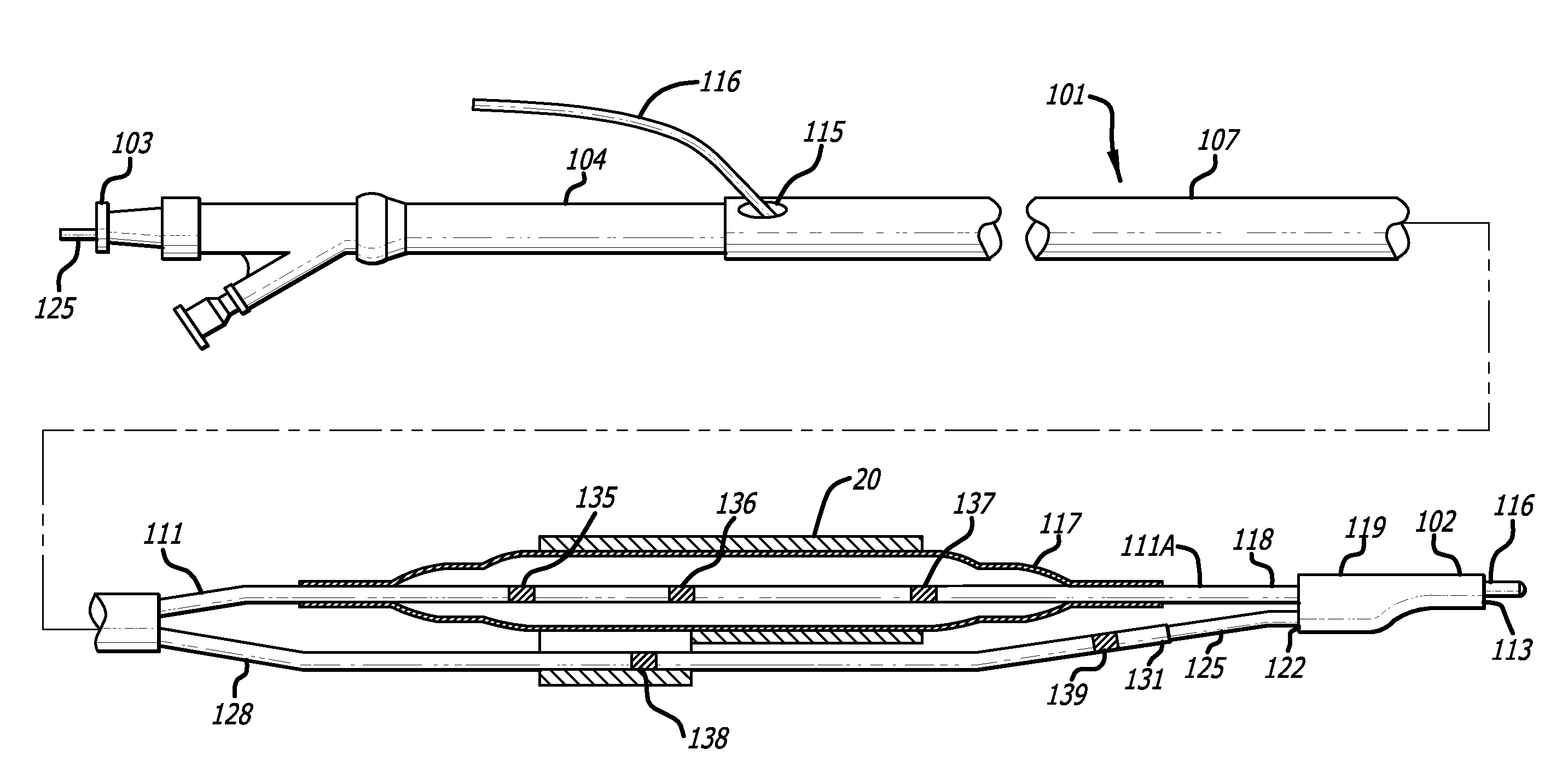
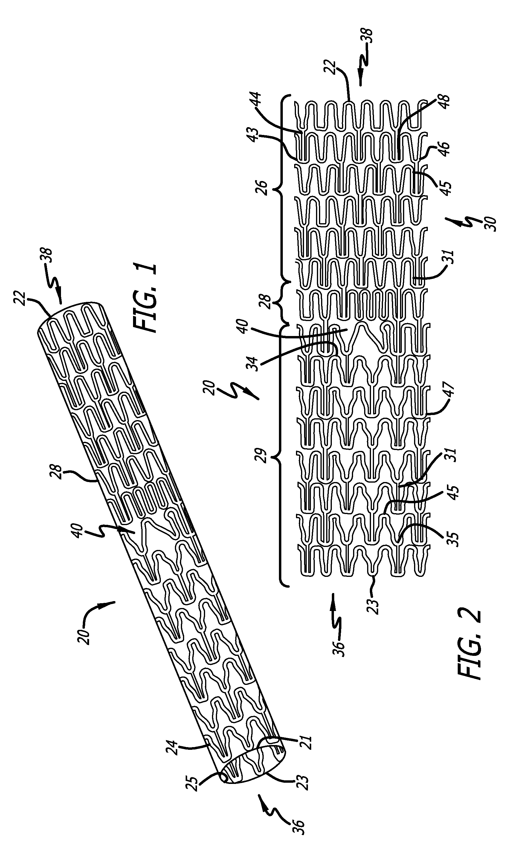
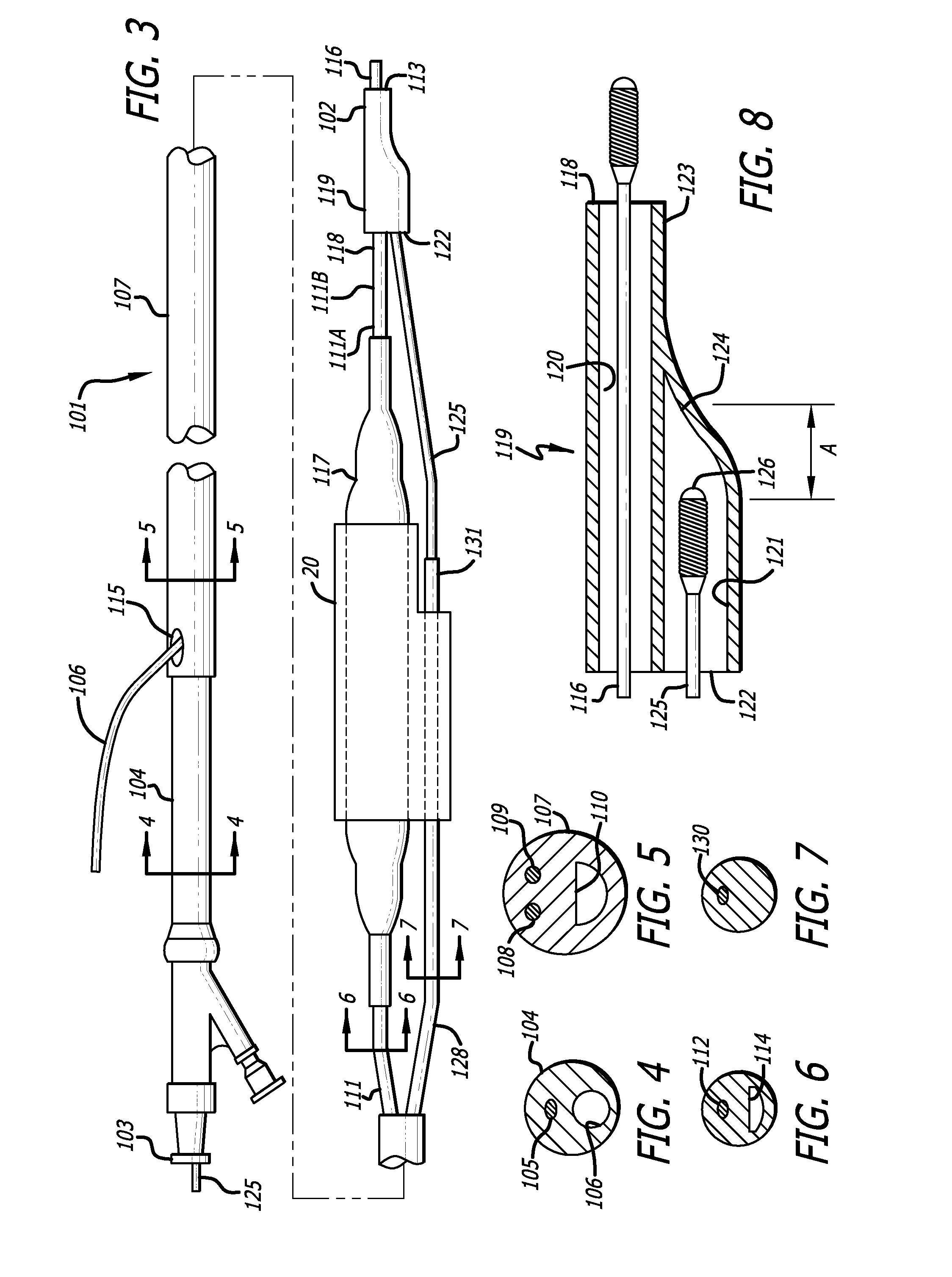
Stent and catheter assembly and method for treating bifurcations

a technology of stents and catheters, applied in the field of stents and stent delivery and deployment assemblies, can solve the problems of affecting the repair of vessels that are diseased at the bifurcation, affecting the radiopacity of markers, and causing restenosis, etc., to achieve the effect of reducing or preventing the flow of polymeric materials, reducing the risk of restenosis, and reducing the risk of diseas

Inactive Publication Date: 2007-12-13
ABBOTT CARDIOVASCULAR
View PDF3 Cites 57 Cited by
  • Summary
  • Abstract
  • Description
  • Claims
  • Application Information

AI Technical Summary

Benefits of technology

[0038]During melt bonding, the polymeric marker is heated to an elevated temperature sufficient to melt the polymeric material to produce the melt bond. However, in one presently preferred embodiment, the elevated temperature is low enough to minimize or prevent flowing of the polymeric material of the marker. Consequently, the double wall thickness (inner diameter minus outer diameter) of the polymeric marker after melt bonding is equal to or not substantially less than (i.e., not more than about 5 to about 25% less than) the double wall thickness prior to melt bonding. Although some rounding of the edges of the polymeric marker may occur during melt bonding, the maximum wall thickness of the polymeric marker is preferably not reduced during the melt bonding. The marker radiopacity is strongly affected by both the percent loading of radiopaque material and the final wall thickness of the marker. Consequently, the percent loading of radiopaque material and the wall thickness of the finished marker are carefully controlled to provide the desired radiopacity. If the wall thickness of the polymeric marker is less than the required minimum wall thickness, the radiopacity of the marker will be too low. On the other hand, if the outer diameter/wall thickness of the polymeric marker is greater than the required maximum outer diameter/wall thickness, the large profile and added stiffness of the marker will disadvantageously affect catheter performance. Thus, the hot die necked extrusion has an outer diameter and wall thickness which is within the minimum and maximum desired values, so that little or no thinning of the marker is required during melt bonding of the marker to provide the desired outer diameter. As a result, a decrease in wall thickness which can reduce the radiopacity of the finished marker is prevented or minimized during bonding. In one embodiment, the polymeric marker is adhesively bonded to the medical device or component, and as a result, the wall thickness of the marker is not affected by the bonding process.
[0039]Due to its high radiopacity, flexibility and melt bondability, the marker of the present invention is readily attached to for example the distal tip of a balloon catheter or a guidewire. The attachment of radiopaque markers at multiple locations on one or more catheter balloons on a bifurcated catheter delivery system with known separation distances impart a measurement capability to the catheter that allows a physician to quickly and easily determine side branch vessel location and access. Markers are positioned so as to enable a physician to determine both the position and orientation of the device. Accordingly, the balloon preferably has a total of three markers attached thereto, corresponding with features of the stent crimped thereto, namely the distal and proximal ends of the stent and the side branch portal. The balloon-less shaft preferably has two markers attached thereto, one at its distal end and another just distal to the side branch portal of the stent crimped thereto.
[0040]The method of delivering and implanting the stent mounted on the catheter assembly are contemplated by the present invention. The bifurcated catheter assembly of the present invention provides two separate shafts in parallel which are advanced into separate passageways of an arterial bifurcation at which point the balloon is inflated to expand and implant the stent. More specifically, and in keeping with the invention, the catheter assembly is advanced through a guiding catheter (not shown) until the distal end of the catheter assembly reaches the ostium to the coronary arteries. An Rx guide wire is advanced out of the Rx shaft and into the coronary arteries to a point distal of the bifurcation or target site. In a typical procedure, the Rx guide wire will already be positioned in the main vessel after a pre dilatation procedure. The catheter assembly is advanced over the Rx guide wire so that the catheter distal end is just proximal to the opening to the side branch vessel. Up to this point in time, the OTW guide wire (or mandrel or joining wire) remains within the catheter assembly and within the coupler so that the shaft with the balloon and the balloon-less shaft remain adjacent to one another to provide a low profile. As the catheter assembly is advanced to the bifurcated area, the coupler moves axially relative to the distal end of the OTW guide wire (or mandrel or joining wire) a small distance (approximately 0.5 mm up to about 5.0 mm), but is not pulled completely out of the coupler, making it easier for the distal end of the catheter to negotiate tortuous turns in the coronary arteries. Thus, the slight axial movement of the coupler ...

Problems solved by technology

Repair of vessels that are diseased at a bifurcation is particularly challenging since the stent must be precisely positioned, provide adequate coverage of the disease, provide access to any diseased area located distal to the bifurcation, and maintain vessel patency in order to allow adequate blood flow to reach the myocardium.
Where the stent provides coverage to the vessel at the diseased portion, yet extends into the vessel lumen at the bifurcation, the diseased area is repaired, but blood flow may be compromised in other portions of the bifurcation.
Unapposed stent elements may promote lumen compromise during neointimal formation and healing, producing restenosis and requiring further procedures.
Moreover, by extending into the vessel lumen at the bifurcation, the stent may block access to further interventional procedures.
Conventional stents are designed to repair areas of blood vessels that are removed from bifurcations, and, therefore are associated with a variety of problems when attempting to use them to treat lesions at a bifurcation.
The drawback with this approach is that there is no way to determine or guarantee that the main vessel stent struts are properly oriented with respect to the side branch or that an appropriate stent cell has been selected by the wire for dilatation.
The aperture created often does not provide a clear opening and creates a major distortion in the surrounding stent struts.
A further drawback with this approach is that there is no way to tell if the main-vessel stent struts have been properly oriented and spread apart to provide a clear opening for stenting the side branch vessel.
This technique also causes stent deformation to occur in the area adjacent to the carina, pulling the stent away from the vessel wall and partially obstructing flow in the originally non jailed vessel.
Deforming the stent struts to regain access into the previously jailed strut is also a complicated and time consuming procedure associated with attendant risks to the patient and is typically performed only if considered an absolute necessity.
The risks of procedural complications during this subsequent deformation are considerably higher than stenting in normal vessels.
The inability to place a guide wire through the jailed lumen in a timely fashion could restrict blood supply and begin to precipitate symptoms of angina or even cardiac arrest.
In addition, platelet agitation and subsequent thrombus formation at the jailed site could further compromise blood flow into the side branch.
This procedure is also associated with the same issues and risks previously described when stenting only...

Method used


Image

  • Stent and catheter assembly and method for treating bifurcations
  • Stent and catheter assembly and method for treating bifurcations
  • Stent and catheter assembly and method for treating bifurcations

Examples


Embodiment Construction

[0064]The present invention includes a stent and stent delivery catheter assembly and method for treating bifurcations in, for example, the coronary arteries, veins, peripheral vessels and other body lumens.

[0065]The stent of the present invention can be implanted in the main or side branch vessels to treat a number of disease configurations at a bifurcation, but not limited to, the following:

[0066]1. Treatment of a parent or main vessel and the origin of the side branch at a bifurcation with any angle associated between the side branch and parent vessel.

[0067]2. Treatment of a parent vessel proximal to the carina and the side branch vessel simultaneously.

[0068]3. Treatment of the proximal vessel extending only into the origin of the side branch and the origin of the distal parent at the bifurcation.

[0069]4. Treatment of the area at the bifurcation only.

[0070]5. The origin of an angulated posterior descending artery.

[0071]6. The origin of an LV extension branch just at and beyond th...


PUM


Abstract

An improved stent design and stent delivery catheter assembly for repairing a main vessel and a side branch vessel forming a bifurcation. The stent is advanced to a bifurcation so that the main stent section is in the main vessel, and the portal section covers at least a portion of the opening to the side branch vessel. A low profile catheter having a branch with an inflation balloon and a balloon-less branch are maintained in a joined configuration during delivery of the catheter to the deployment site. Radiopaque markers on the balloon and on the balloon-less shaft enable the longitudinal and rotational orientation of the assembly to be fluoroscopically envisioned. The inflation of the balloon causes the stent to be expanded while the presence of the balloon-less shaft causes the stent's side portal to be opened sufficiently to allow for a subsequent expansion procedure.

Description

CROSS-REFERENCES TO RELATED APPLICATIONS[0001]This application claims the benefit of U.S. Provisional Application Ser. No. 60 / 811,699, filed Jun. 7, 2007; the contents of which is hereby incorporated herein by reference.BACKGROUND OF THE INVENTION[0002]The invention relates to stents and stent delivery and deployment assemblies for use at a bifurcation and, more particularly, one or more stents for repairing bifurcations, blood vessels that are diseased, and a method and apparatus for delivery and implantation of the stents.[0003]Stents conventionally repair blood vessels that are diseased. Stents are generally hollow and cylindrical in shape and have terminal ends that are generally perpendicular to their longitudinal axis. In use, the conventional stent is positioned at the diseased area of a vessel and, after deployment, the stent provides an unobstructed pathway for blood flow.[0004]Repair of vessels that are diseased at a bifurcation is particularly challenging since the stent ...

Claims


Application Information

Patent Timeline
IPC IPC(8): A61F2/84
CPCA61F2/856A61F2250/006A61F2/958A61F2/954A61F2250/0098
Inventor WILLIAMS, MARK A.
Owner ABBOTT CARDIOVASCULAR
Why Eureka
Try Eureka