Loop type heat pipe and waste heat recovery device

Inactive Publication Date: 2007-12-20
DENSO CORP
View PDF0 Cites 21 Cited by
  • Summary
  • Abstract
  • Description
  • Claims
  • Application Information

AI Technical Summary

Benefits of technology

[0012] According to another example of the present invention, a waste heat recovery device includes: a loop-type heat pipe including an evaporator located to evaporate a refrigerant by performing a heat exchange with a first fluid, and a condenser located to cool and condense the evaporated vapor refrigerant from the evaporator; a first fluid flowing portion in which the first fluid flows to perform heat exchange with the refrigerant flowing in the evaporator; a second fluid flowing portion in which the second fluid flows to perform heat exchange with the refrigerant flowing in the condenser; an introducing pipe for introducing the second fluid to the second fluid flowing portion; and a discharging pipe for discharging the second fluid from the second fluid flowing portion after passing through the second fluid flowing portion. Furthermore, the condenser has a refrigerant condensation side on which the condensed liquid refrigerant flows,

Problems solved by technology

Furthermore, the loop type heat pipe is provided with a flow limitation means for flowing the s

Method used


Image

  • Loop type heat pipe and waste heat recovery device
  • Loop type heat pipe and waste heat recovery device
  • Loop type heat pipe and waste heat recovery device

Examples


Example

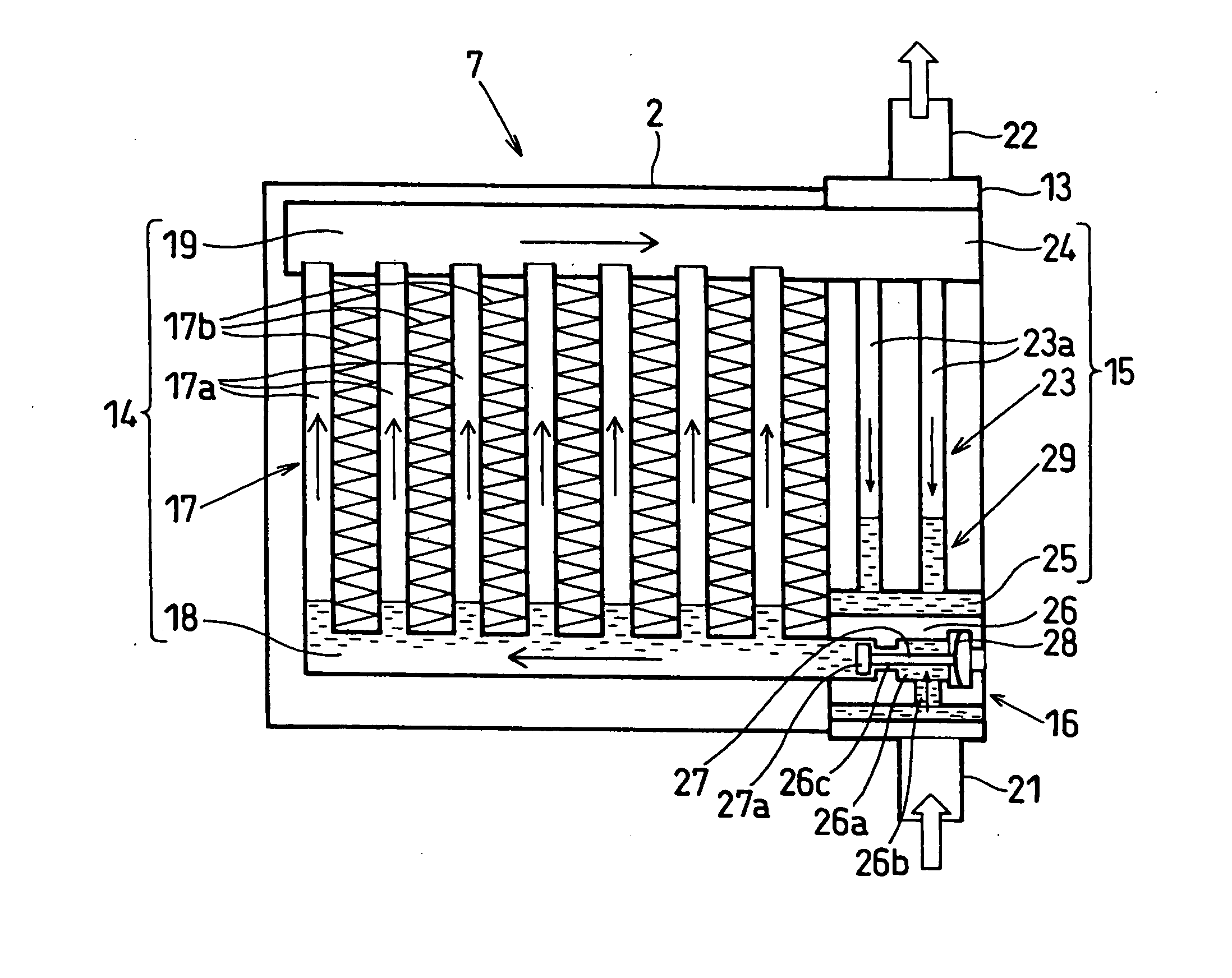
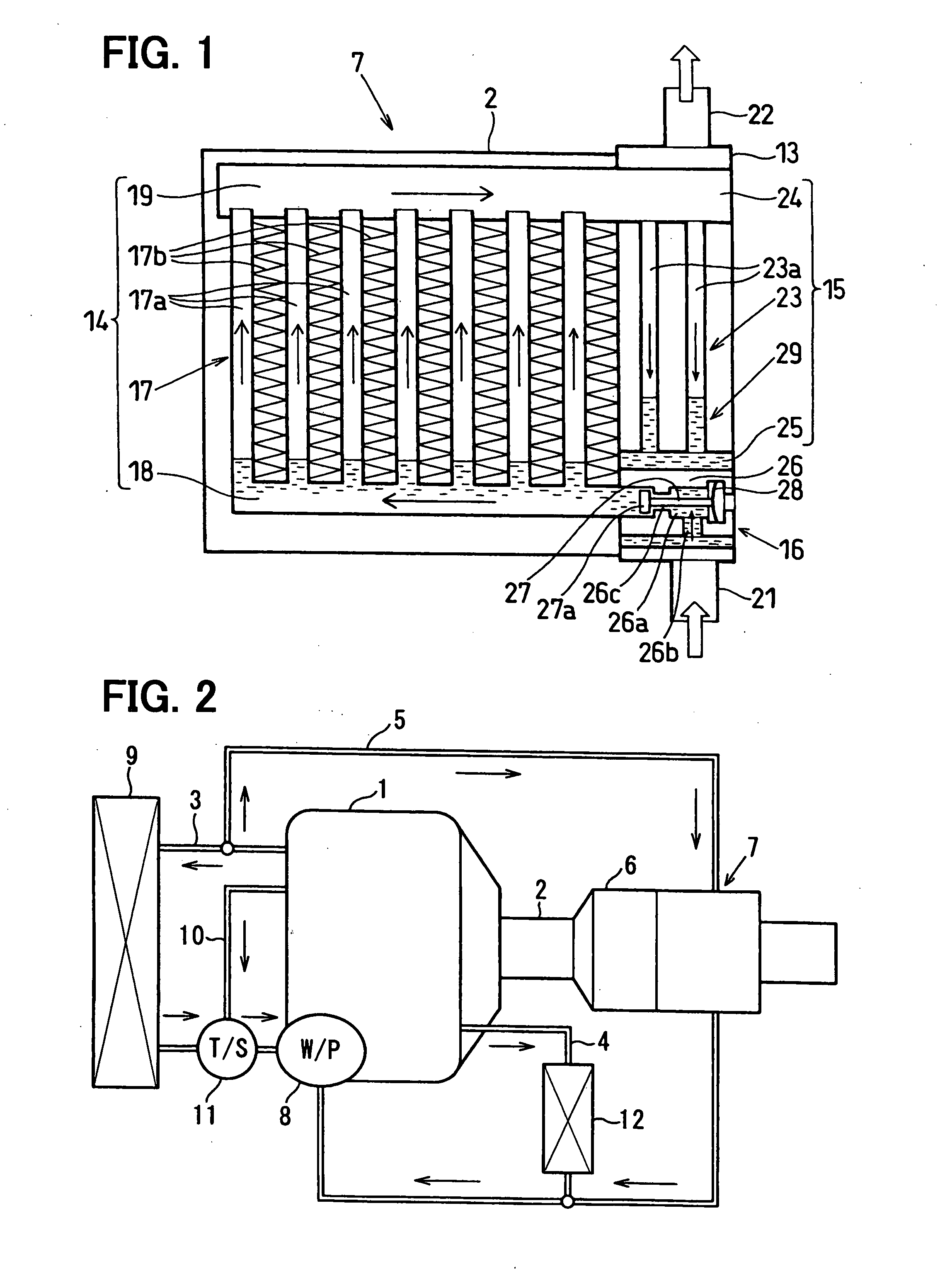
[0018] A first embodiment will be now described with reference to FIGS. 1 and 2. In this embodiment, a loop type heat pipe is typically used for a waste heat recovery device.

[0019] First, a basic structure of the waste heat recovery device will be now described. An engine (internal combustion engine) 1 is located for generating a rotation output for a vehicle running by fuel combustion. The engine 1 is generally provided with a coolant circuit for controlling heat generated in the engine 1, and an exhaust pipe 2 for discharging exhaust gas to atmosphere.

[0020] The coolant circuit includes a radiator circuit 3, a heater circuit 4 and a waste heat recovery circuit 5. Furthermore, a catalytic converter 6 for purifying the exhaust gas and the waste heat recovery device 7 are located in the exhaust pipe 2.

[0021] Next, the coolant circuit including the radiator circuit 3, the heater circuit 4 and the waste heat recovery circuit 5 will be described.

[0022] A radiator 9 is located to per...

Example

Second Embodiment

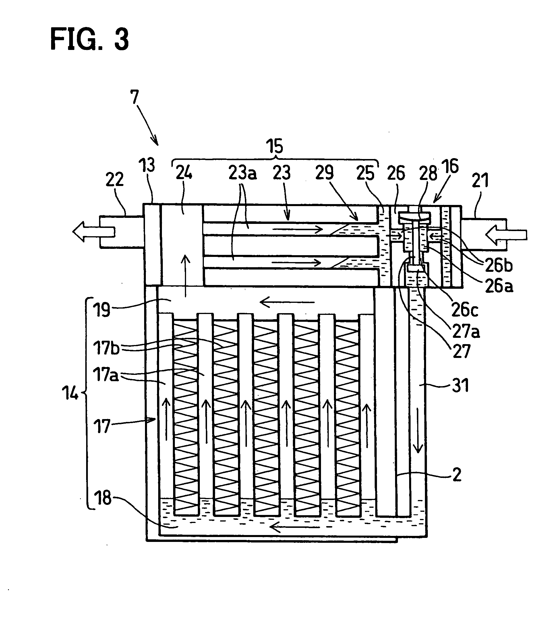
[0061] The second embodiment will be described with reference to FIG. 3. In the second embodiment, members having the same functions as those of the above-described first embodiment are indicated by the same reference numbers.

[0062] In the waste heat recovery device 7 of the above-described first embodiment, the tubes 23a of the condenser 15 are elongated in the vertical direction so that liquid refrigerant moves downwardly by its weight when the waste heat recovery device 7 is mounted on a vehicle. That is, in the above-described first embodiment, the condenser 15 is located on the side surface of the evaporator 14 such that the tubes 17a of the evaporator 14 and the tubes 23a of the condenser 15 are arranged in parallel with each other to be elongated in the vertical direction when the waste heat recovery device 7 is mounted on a vehicle. However, in the second embodiment, the condenser 15 is located such that the longitudinal direction of the tubes 23a of the c...

Example

Third Embodiment

[0069] A third embodiment will be now described with reference to FIG. 4. In the above-described first and second embodiments, the differential pressure regulating valve 16 is used as one example of the operation stop means of the waste heat recovery device 7, to open and close the communication passage through which the liquid refrigerant condensed in the condenser 15 flows to the evaporator 14. However, in a waste heat recovery device 7 of the third embodiment, as shown in FIG. 4, the differential pressure regulating valve 16 is not provided. In the third embodiment, an operation stop means for stopping evaporation of the refrigerant in the evaporator 14 is constructed without using the differential pressure regulating means 16. For example, a fluid control means for controlling a supply amount of exhaust gas (first fluid for heating) introduced to the evaporator 14 through the exhaust gas pipe 2 is provided so as to stop the evaporation of refrigerant in the evap...


PUM


Abstract

A loop type heat pipe includes an evaporator located to evaporate a refrigerant by heat-exchanging with a first fluid as a heat source, and a condenser located to liquefy and condense the evaporated vapor refrigerant by heat-exchanging with a second fluid to be heated. The condenser has a refrigerant condensation side on which the condensed liquid refrigerant flows, and a refrigerant un-condensation side on which the vapor refrigerant before being condensed flows. In addition, the loop type heat pipe is provided with a flow limitation portion for flowing the second fluid from the refrigerant condensation side toward the refrigerant un-condensation side. For example, the loop type heat pipe is suitably used for a waste heat recovery device.

Description

CROSS REFERENCE TO RELATED APPLICATION [0001] This application is based on Japanese Patent Application No. 2006-165177 filed on Jun. 14, 2006, the contents of which are incorporated herein by reference in its entirety. BACKGROUND OF THE INVENTION [0002] 1. Field of the Invention [0003] The present invention relates to a loop type heat pipe, in which a refrigerant is evaporated by heat from a first fluid as a heat source, and the evaporated vapor refrigerant is cooled by a second fluid to be heated so as to heat the second fluid by condensation latent heat of the vapor refrigerant. For example, the loop type heat pipe can be suitably used for a waste heat recovery device. [0004] 2. Description of the Related Art [0005] Conventionally, a loop type heat pipe is described in JP-A-4-45393, for example. This loop type heat pipe is provided with an evaporator for heating and evaporating refrigerant, and a condenser for cooling and condensing the evaporated vapor refrigerant. Furthermore, o...

Claims


Application Information

Patent Timeline
IPC IPC(8): F28D15/00
CPCF28D21/0003F28D15/0266
Inventor MIYAGAWA, MASASHIYAMANAKA, YASUTOSHIINOUE, SEIJIKOHARA, KIMIO
Owner DENSO CORP
Why Eureka
Try Eureka