
Light Emitting Diode having vertical topology and method of making the same

Active Publication Date: 2007-12-27
SUZHOU LEKIN SEMICON CO LTD +1
View PDF20 Cites 97 Cited by
  • Summary
  • Abstract
  • Description
  • Claims
  • Application Information

AI Technical Summary

Benefits of technology

[0023]An object of the present invention is to provide a method of making an LED having vertical topology that is capable of efficiently achieving substrate separation and is also capable of ensuring a structural stability of the device, in a separation process between a sapphire substrate and a GaN-based semiconductor layer, which is desired in the manufacture of an LED having a vertical structure. Therefore, the present invention may make a great contribution to structural characteristics and reliability of the semiconductor from which the substrate was separated, and may also remarkably improve a stable separation yield and thereby productivity.
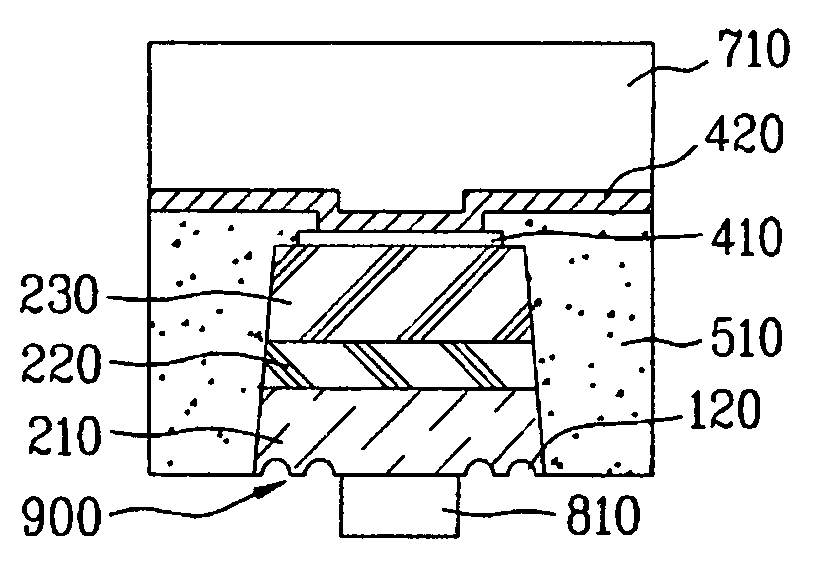
[0024]Another object of the present invention is to provide an LED having vertical topology and method of making the same, which are not only capable of significantly improving a light-extraction efficiency and but are also capable of controlling luminescence properties and light patterns of a device, via the introduction of various structures for improving light-extraction.

Problems solved by technology

Despite the rapid advancement in technologies of GaN-based semiconductor devices, the fabrication of GaN-based devices suffers from a great disadvantage in terms of high-production costs.
This disadvantage is closely related to difficulties associated with growing GaN epitaxial layers and subsequent cutting of finished GaN-based devices.
Meanwhile, because sapphire is an insulating material, the use of sapphire substrate (or any other insulating substrate) practically limits the LED device using the insulating substrate to a lateral structure.
However, the LED having the lateral structure or the LED fabricated using the flip chip method suffers from problems associated with poor heat release efficiency because the sapphire substrate has heat conductivity of about 27 W / mK, thus leading to very high heat resistance.
Further, the flip chip method has additional disadvantages of requiring large numbers of photolithography process steps, thus resulting in complicated manufacturing processes.
Even though the laser lift-off process has advantages of remarkably reducing the number of the manufacturing process steps and providing excellent luminescence properties, such a conventional laser lift-off process damages the crystal structure of the LED due to thermal stress occurring between the sapphire substrate and LED structure when performing laser irradiation.
Further, nitrogen (N2) gas, separated and discharged from Ga upon performing laser irradiation, passes through the LED structure, which leads to damage of the LED crystal structure, and thus significantly reduces production yield and consequently makes it difficult to realize mass production.

Method used


Image

  • Light Emitting Diode having vertical topology and method of making the same
  • Light Emitting Diode having vertical topology and method of making the same
  • Light Emitting Diode having vertical topology and method of making the same

Examples


Embodiment Construction

[0046]The present invention now will be described more fully hereinafter with reference to the accompanying figures, in which embodiments of the invention are shown. This invention may, however, be embodied in many alternate forms and should not be construed as limited to the embodiments set forth herein. Accordingly, while the invention is susceptible to various modifications and alternative forms, specific embodiments thereof are shown by way of example in the drawings and will herein be described in detail. It should be understood, however, that there is no intent to limit the invention to the particular forms disclosed, but on the contrary, the invention is to cover all modifications, equivalents, and alternatives falling within the spirit and scope of the invention as defined by the claims.

[0047]Like numbers refer to like elements throughout the description of the figures. In the drawings, the thickness of layers and regions are exaggerated for clarity.

[0048]It will be understo...


PUM


Abstract

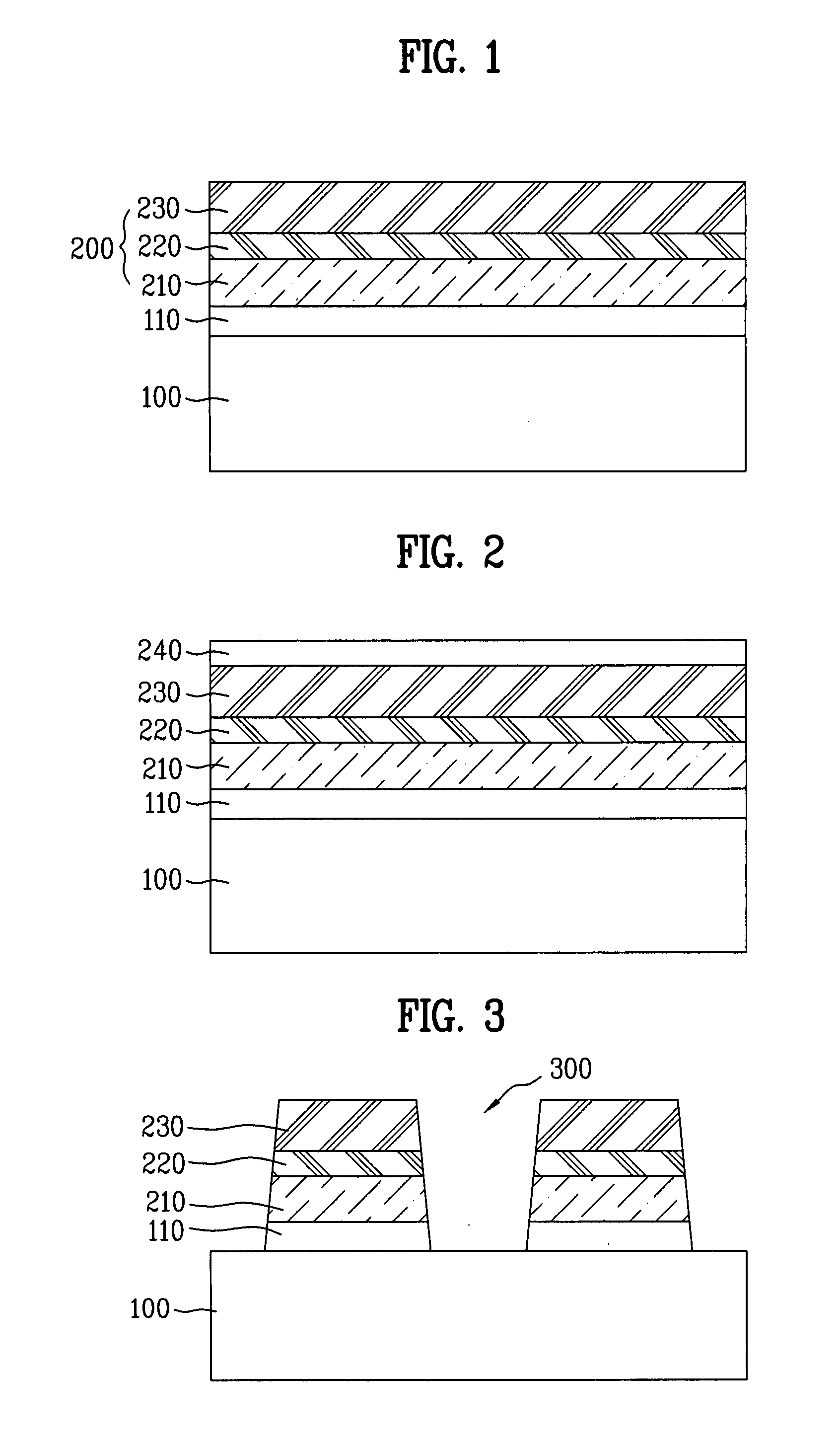
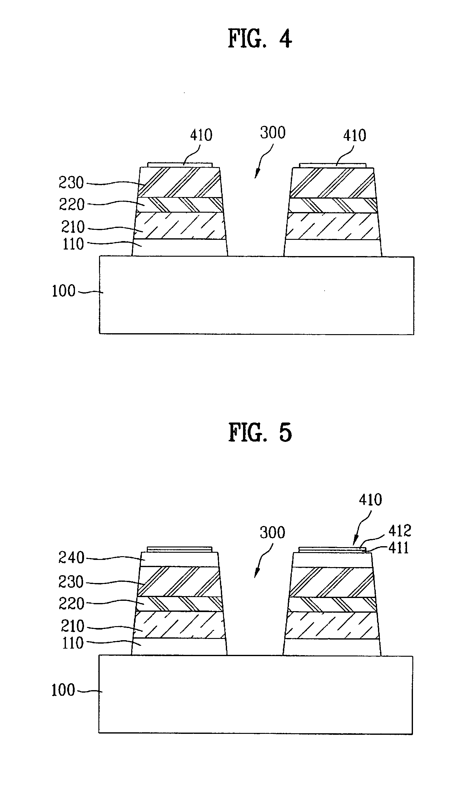
An LED having vertical topology and a method of making the same is capable of improving a luminous efficiency and reliability, and is also capable of achieving mass productivity. The method includes forming a semiconductor layer on a substrate; forming a first electrode on the semiconductor layer; forming a supporting layer on the first electrode; generating an acoustic stress wave at the interface between the substrate and semiconductor layer, thereby separating the substrate from the semiconductor layer; and forming a second electrode on the semiconductor layer exposed by the separation of the substrate.

Description

[0001]This application claims the benefit of Korean Patent Application No. 10-2006-0057033, filed on Jun. 23, 2006, Korean Patent Application No. 10-2006-0093465, filed on Sep. 26, 2006, and Korean Patent Application No. 10-2006-0093574, filed on 2006, which are all hereby incorporated by reference as if fully set forth herein.BACKGROUND OF THE INVENTION[0002]1. Field of the Invention[0003]The present invention relates to an LED having vertical topology, and more particularly, to an LED having vertical topology that is capable of achieving high luminous efficiency and reliability thereof, and is also capable of improving mass productivity, and a method of making the same.[0004]2. Discussion of the Related Art[0005]Light Emitting Diodes (LEDs) are well-known semiconductor light-emitting devices that convert electric current into light. They have been used as light sources for display image of electronic equipment including information communication equipment, since the commercializat...

Claims


Application Information

Patent Timeline
IPC IPC(8): H01L33/00H01L33/20
CPCH01L33/0079H01L33/22H01L33/405H01L33/04H01L33/40H01L2933/0083H01L2933/0016H01L33/20H01L33/0093H01L33/0075H01L33/06H01L33/32H01L33/38H01L33/44
Inventor JANG, JUN HOCHOI, JAE WANBAE, DUK KYUCHO, HYUN KYONGPARK, JONG KOOKKIM, SUN JUNGLEE, JEONG SOO
Owner SUZHOU LEKIN SEMICON CO LTD
Learn More