Method and apparatus for regulating voltage

a voltage regulator and voltage technology, applied in the direction of electric variable regulation, process and machine control, instruments, etc., can solve the problems of circuits, circuits, and devices being damaged,

Inactive Publication Date: 2007-12-27
ELECTRO CHANCE
View PDF5 Cites 23 Cited by
  • Summary
  • Abstract
  • Description
  • Claims
  • Application Information

AI Technical Summary

Benefits of technology

[0007] The present invention addresses the above deficiencies associated with the prior art and discloses a voltage regulator and methods of regulating voltage providing any type of a given electrical load with a desired voltage output within a predetermined range. The AC voltage regulator in accordance with one embodiment of the present invention performs with any loads without any power interruptions during any transition time, without distortion of the AC sine wave, and without harmful high amounts of current circulating through the circuit components during switching.

Problems solved by technology

This is especially important to sensitive electrical devices that may become damaged if the voltage is not maintained properly.
Problems arise when the device switches from one mode of operation to another mode (for example, switching from normal mode to a step-up mode) momentarily disconnecting the power source from the load or producing transient currents that electrically saturate part of the circuit.
This can cause momentary power interruptions or overload parts of the circuit causing damage to the device.
With higher power, the circuit will face typical disadvantages such as oversaturation without appreciable voltage regulation during the switching transient, wave form distortion and questionable dependability.
None of these devices disclose a means for preventing electrical overloads or power interruptions during the brief periods when the switches or relays switch from one configuration to another.
Thus, it is unlikely these systems can be widely used with industrial systems.

Method used


Image

  • Method and apparatus for regulating voltage
  • Method and apparatus for regulating voltage
  • Method and apparatus for regulating voltage

Examples


Embodiment Construction

[0025] The present invention will now be described more specifically with references to the figures. It is to be noted that the following descriptions of preferred embodiments of this invention are presented herein for purposes of illustration and description only; it is not intended to be exhaustive or to be limited to the precise forms disclosed, since the voltage regulator according to the invention may be advantageously used and modified in various fields.

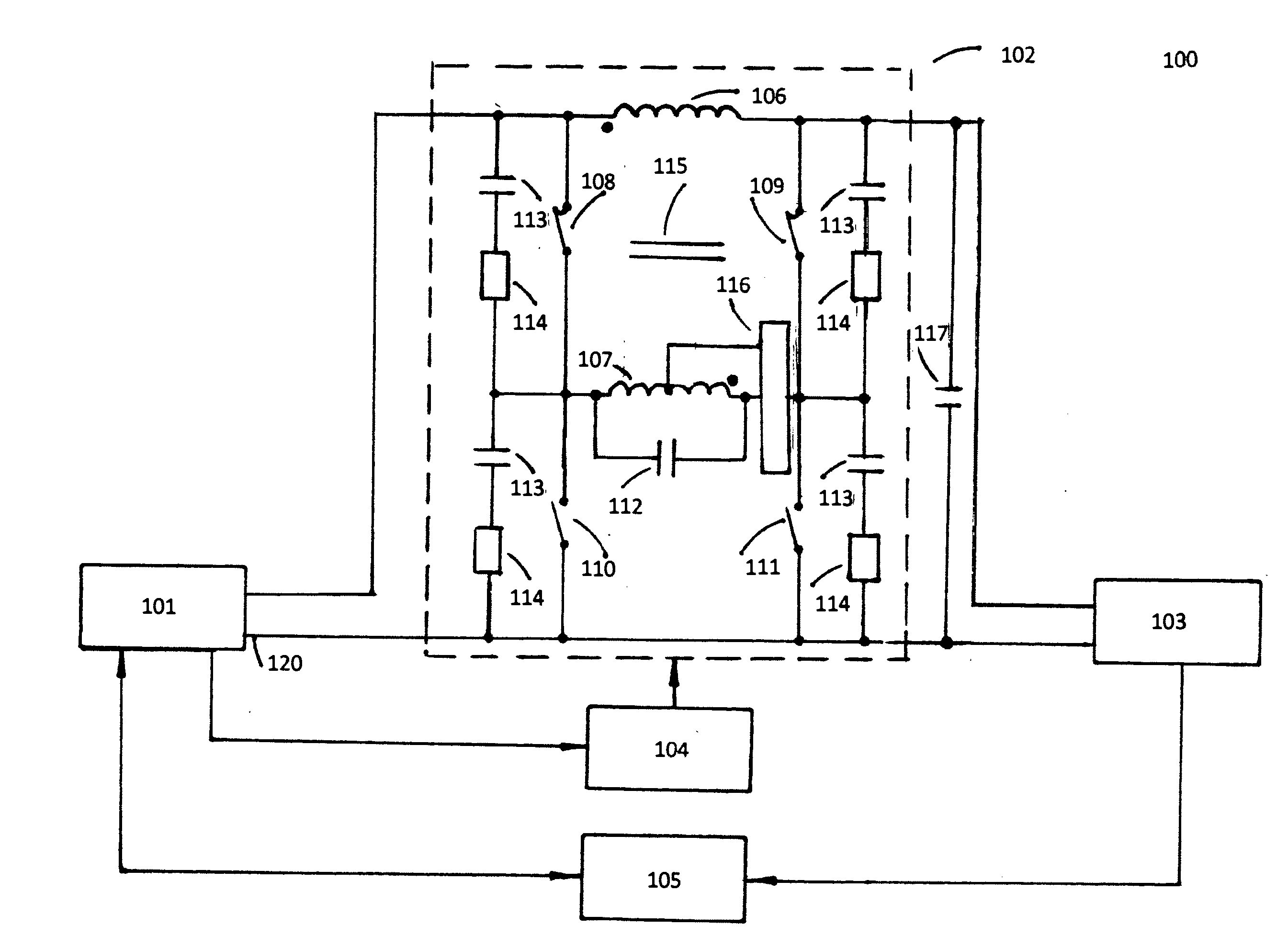
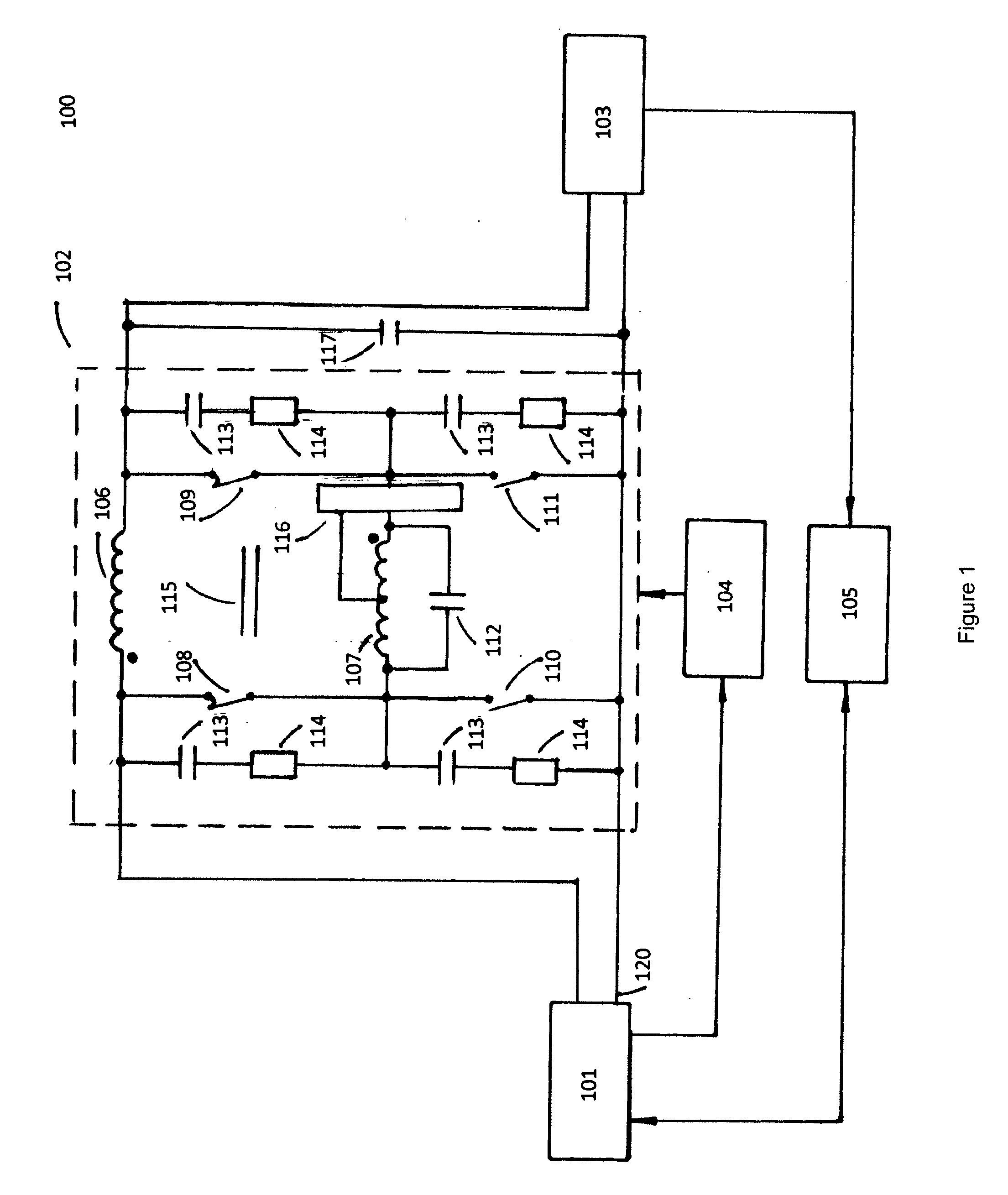
[0026]FIG. 1 illustrates a voltage regulator 100 in one embodiment of the present invention comprising a power circuit 102 and a control circuit 104. The voltage regulator 100 has an input that is electrically connected with the AC power source 101 in any conventional manner and an output that is connected with the electrical load 103. The control circuit 104 can be any control circuit known in the art and is electrically connected with the power circuit 102 and the AC power source 101. A protection circuit 105 is also electri...


PUM


Abstract

An AC voltage regulator able to provide a desired voltage to any type of a given load within a predetermined range without any output power interruptions during any transition time, without distortion of the AC sine wave and without high current circulating through the circuit components during the voltage switching. The voltage regulator uses a single regulator transformer having a primary winding and a secondary winding. The secondary winding of the regulator transformer is connected in series between a power source and the load, while the primary winding of the regulator transformer is connected with the power source so that the primary and secondary windings have opposite polarities. The position of a plurality of switches can be variably set by the control circuit to control current flow through the primary winding and to provide a normal mode, a step-down mode, or a step-up mode.

Description

CROSS-REFERENCE TO RELATED APPLICATIONS [0001] This application claims benefit of U.S. Provisional Application No. 60 / 805,712, filed Jun. 23, 2006, which is incorporated in its entirety herein to the extent that there is no inconsistency with the present disclosure.BACKGROUND OF THE INVENTION [0002] This invention generally pertains to voltage regulators, and more particularly AC voltage regulators able to provide a desired AC voltage to any type of a given load, without any output power interruptions during any regulation period and without distortion of the AC sine wave. The benefits associated with the use of the present invention include reduced size and cost of the voltage regulating devices, reduced electrical energy consumption and increased equipment life in electrical installations. [0003] A voltage regulator is designed to deliver and automatically maintain a constant voltage level to a load. If the incoming voltage is too high or too low compared to a desired predetermine...

Claims


Application Information

Patent Timeline
Patent Type & Authority Applications(United States)
IPC IPC(8): G05F1/14G05F1/00
CPCH02M5/22H02M5/12
Inventor FEIGIN, LEV Z.KOSOY, PETR L.KLAVSUTS, DMITRIY A.LEVINZON, SULEYMAN V.
Owner ELECTRO CHANCE
Why Eureka
Try Eureka