

Laser plasma spectroscopy apparatus and method for in situ depth profiling
- Summary
- Abstract
- Description
- Claims
- Application Information
AI Technical Summary
Problems solved by technology
Method used
Image

Examples
examples
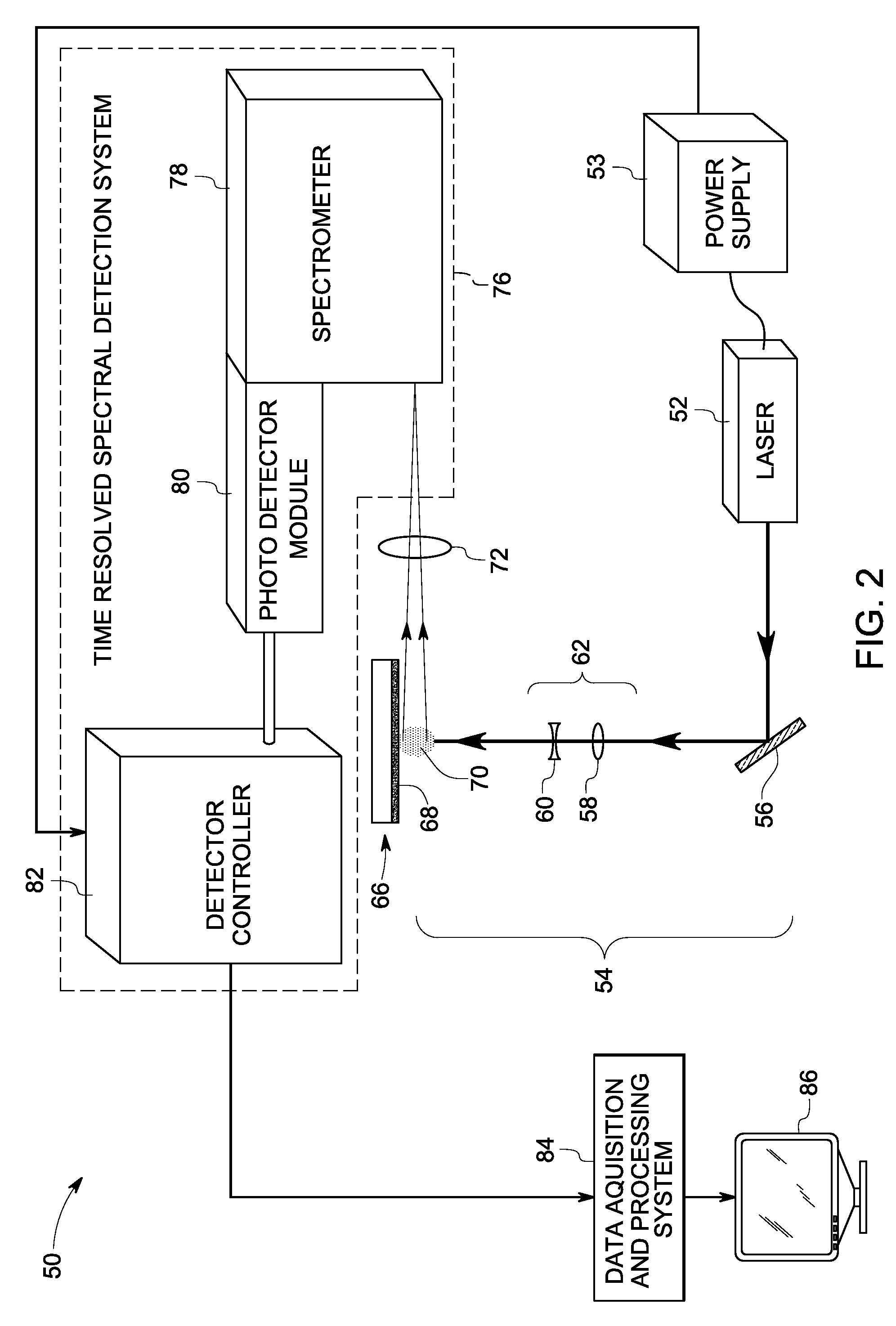
[0049]A “free space” optical probe system configuration of the laser plasma spectroscopy system as shown in FIG. 2 was built in accordance with one embodiment of the present invention. The system included a Nd:YAG laser configured to emit ˜45 mJ laser pulses at a wavelength of 1064 nm at 20 Hz repetition rate. A collimating element including positive and negative lenses was used to generate a collimated beam of about 600 microns in diameter with a flat topped uniform intensity profile. As used herein the term “flat topped uniform intensity profile” refers to an intensity profile capable of producing an optical illumination zone of substantially uniform optical energy for target ablation with one example being shown in FIGS. 6 and 7. FIG. 6 shows the 3 dimensional (3D) profile of the ˜45 mJ laser beam pulses at a target surface distance. The 3D plot of the intensity 118 versus the beam spot dimensions along the Y-axis 120 and X-axis 122 shows a substantially flat-topped, uniform inte...
PUM
 Abstract
Description
Claims
Application Information