Method of Producing Light-Scattering Film, Polarizing Plate Comprising Light-Scattering Film and Liquid Crystal Display Device Comprising the Polarizing Plate

a technology of light-scattering film and polarizing plate, which is applied in the direction of polarizing elements, instruments, transportation and packaging, etc., can solve the problems of too high sedimentation rate of light-transmitting particulate material, and no method of producing light-scattering film having uniform in-plane scattering properties, etc., to achieve high productivity

Inactive Publication Date: 2007-12-27
FUJIFILM CORP
View PDF9 Cites 28 Cited by
  • Summary
  • Abstract
  • Description
  • Claims
  • Application Information

AI Technical Summary

Benefits of technology

[0197] The content of the sol component of organosilane compound in the low refractive layer is preferably from 5 to 100% by mass, more preferably from 5 to 40% by mass, even more preferably from 8 to 35% by mass, particularly from 10 to 30% by mass based on the mass of the fluorine-containing polymer. When the content of the sol component is too low, the effect of the invention can be difficulty exerted. On the contrary, when the content of the sol component is too high, the resulting low refractive layer exhibits a raised refractive index and deteriorated film shape and surface conditions to disadvantage.
[0198] The aforementioned curable composition may comprise an inorganic filler other than the aforementioned inorganic particulate material incorporated therein in an amount such that the desired effect of the invention cannot be impaired. The inorganic filler will be further described later. (Sol-Gel Material)
[0199] As the materials constituting the low refractive layer there may be also used various sol-gel materials. As these sol-gel materials there may be used metal alcoholates (alcoholate of silane, titanium, aluminum, zirconium, etc.), organoalkoxy metal compounds and hydrolyzates thereof. Particularly preferred among these sol-gel materials are alkoxysilane, organoalkoxysilane and hydrolyzates thereof. Examples of these sol-gel materials include tetraalkoxysilanes (e.g., tetramethoxysilane, tetraethoxysilane), alkyltrialkoxysilanes (methyl trimethoxysilane, ethyl trimethoxysilane), aryl trialkoxysilanes (e.g., phenyl trimethoxysilane), dialkyl dialkoxysilanes, and diaryl dialkoxysilanes. Other examples of these sol-gel materials employable herein include organoalkoxysilanes having various functional groups (e.g., vinyl trialkoxysilane, methyl vinyl dialkoxysilane, γ-glycidyloxy propyl trialkoxysilane, γ-glycidyloxy propyl methyl dialkoxysilane, β-(3,4-epoxydicyclohexyl)ethyl trialkoxysilane, γ-methacryloyloxypropyl trialkoxysilane, γ-aminopropyl trialkoxysilane, γ-mercaptopropyl trialkoxysilane, γ-chloropropyl trialkoxysilane), and perfluoroalkyl group-containing silane compounds (e.g., (heptadecafluoro-1,1,2,2-tetradecyl)triethoxysilane, 3,3,3-trifluoropropyl trimethoxysilane). In particular, the use of a fluorine-containing silane compound is advantageous in the reduction of refractive index of layer and the provision of water repellency and oil repellency. [Other Materials to be Incorporated in Curable Composition for Low Refractive Layer]
[0200] The aforementioned curable composition is prepared by dissolving the aforementioned fluorine-containing polymer (A), inorganic particulate material (B) and organosilane compound (C) and optionally various additives, a radical polymerization initiator and a cationic polymerization initiator in a proper solvent. The concentration of solid content is properly predetermined depending on the purpose but is normally from about 0.01 to 60% by mass, preferably from about 0.5 to 50% by mass, particularly from about 1 to 20% by mass.
[0201] From the standpoint of interfacial adhesion to the underlying layer with which the low refractive layer comes in direct contact, the curable composition may comprise a curing agent such as polyfunctional (meth)acrylate, polyfunctional epoxy compound, polyisocyanate compound, aminoplast, polybasic acid and anhydride thereof incorporated therein in a small amount. The amount of the curing agent, if used, is preferably 30% by mass or less, 20% by mass or less, 10% by mass or less based on the total solid content of the low refractive layer.
[0202] For the purpose of providing properties such as stainproofness, water resistance, chemical resistance and slipperiness, a known silicone-based or fluorine-based stainproofing agent, a lubricant or the like may be properly added. These additives, if any, are preferably added in an amount of from 0.01 to 20% by mass, more preferably from 0.05 to 10% by mass, particularly from 0.1 to 5% by mass based on the solid content of the low refractive layer.

Problems solved by technology

As mentioned above, no method of producing a light-scattering film having uniform in-plane scattering properties using a die coating method that attains a high productivity has been proposed.
As a result, an idea was reached that the aforementioned problems are attributed to too high a sedimentation rate of light-transmitting particulate material.

Method used

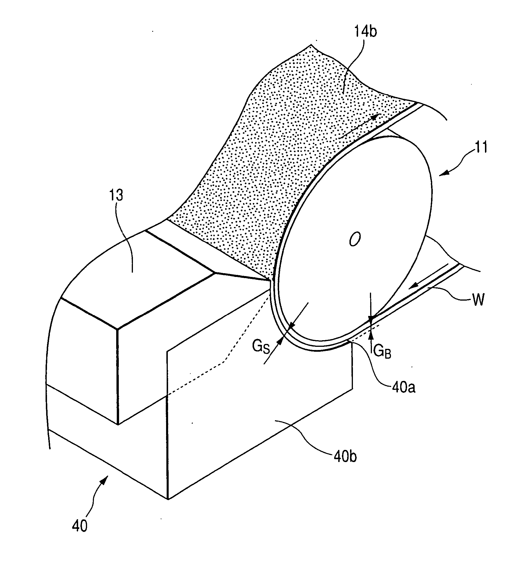
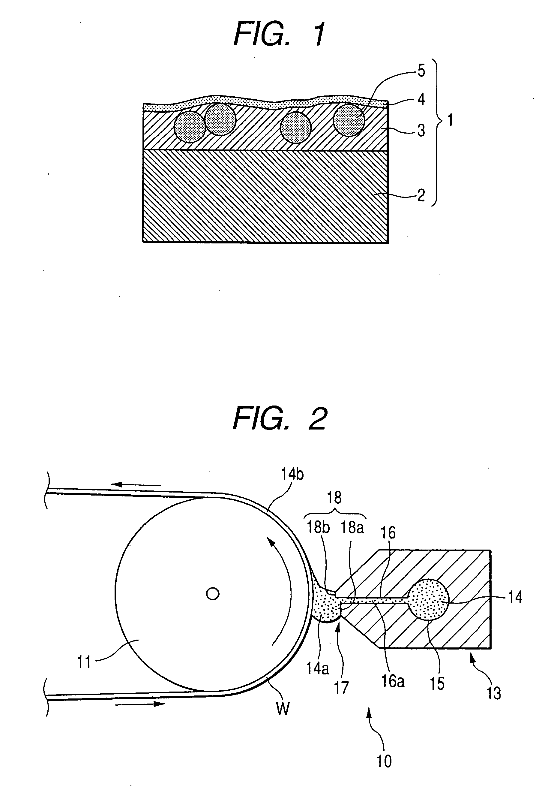
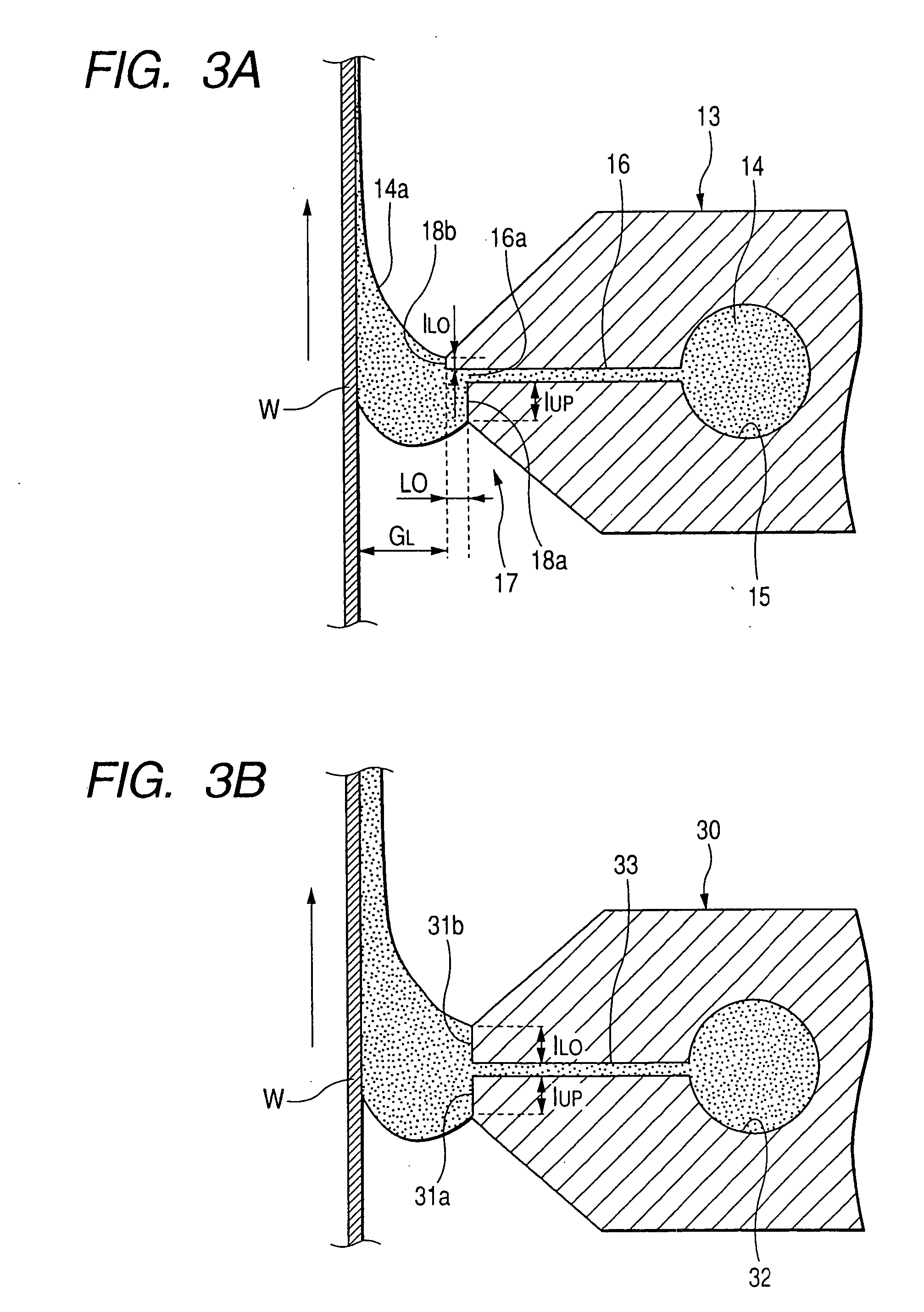

Image

  • Method of Producing Light-Scattering Film, Polarizing Plate Comprising Light-Scattering Film and Liquid Crystal Display Device Comprising the Polarizing Plate
  • Method of Producing Light-Scattering Film, Polarizing Plate Comprising Light-Scattering Film and Liquid Crystal Display Device Comprising the Polarizing Plate
  • Method of Producing Light-Scattering Film, Polarizing Plate Comprising Light-Scattering Film and Liquid Crystal Display Device Comprising the Polarizing Plate

Examples


example 1

(1) Spreading of Light-Scattering Layer

[0348] The coating solution for light-scattering layer A was spread over a triacetyl cellulose film having a thickness of 80 μm (TAC-TD80UF”, produced by Fuji Photo Film Co., Ltd.) using a die coating method involving the use of the following device configuration under coating conditions. The coating layer was dried at 30° C. for 15 second and then at 90° C. for 20 second, and then irradiated with ultraviolet rays at an illuminance of 400 mW / cm2 and a dose of 90 mJ / cm2 using a 160 W / cm air-cooled metal halide lamp (produced by EYE GRAPHICS CO., LTD.) while the air in the system was being purged with nitrogen to undergo curing so that an anti-glare light-scattering layer was formed to a thickness of 6 μm. The film was then wound. Thus, Example 1-1 was effected.

[0349] Light-scattering layers were prepared in the same manner as mentioned above except that the light-scattering layer coating solution A was replaced by the light-scattering layer co...

example 2

[0366] A triacetyl cellulose film having a thickness of 80 μm (TAC-TD80U, produced by Fuji Photo Film Co., Ltd.) which had been dipped in a 1.5 mol / l aqueous solution of NaOH kept at 55° C. for 2 minutes, neutralized and rinsed and the light-scattering film (Examples 1-1 and 1-2) and anti-reflection film (saponified; Examples 1-3 to 1-12) prepared in Example 1 were bonded to the both sides of a polarizer prepared by adsorbing iodine to a polyvinyl alcohol which was then stretched to protect the polarizer. Thus, a polarizing plate was prepared. These polarizing plates were each used to prepare a transmission type TN liquid crystal display device having a light-scattering layer or anti-reflection layer disposed on the outermost layer thereof. These transmission type TN liquid crystal display devices caused no reflection of external light and thus exhibited an excellent viewability. In particular, the transmission type TN liquid crystal display devices having an anti-reflection film di...

example 3

[0367] As each of the protective film to be disposed on the liquid crystal side of the polarizing plate on the viewing side and the protective film to be disposed on the liquid crystal side of the polarizing plate on the backlight side of the transmission type TN liquid crystal cell of Example 2 there was used a viewing angle widening film (Wide View Film SA 12B, produced by Fuji Photo Film Co., Ltd.). As a result, a liquid crystal display device having very wide horizontal and vertical viewing angles, an extremely excellent viewability and a high display quality was obtained.

[0368] Using a Type GP-5 goniophotometer (produced by MURAKAMI COLOR RESEARCH LABORATORY), the film disposed perpendicular to incident light was then measured for scattered light profile in all the directions. From this profile was then determined the intensity of scattered light at an angle of 30° with respect to an emission angle of 0°. Examples 1-2, 1-4 and 1-9 to 1-12 (Samples comprising the light-scatteri...


PUM

PropertyMeasurementUnit
particle diameteraaaaaaaaaa
land lengthaaaaaaaaaa

Abstract

A method of producing a light-scattering film, comprising: disposing a land of a forward end lip of a slot die close to a surface of a web; and applying a coating composition on the web through a slot of the forward end lip, so as to provide the coating composition directly or indirectly on the transparent support, wherein the web is being continuously running while being supported on a backup roll, and wherein the coating composition comprises a light-transmitting particulate material, a transmitting resin and a solvent, and the coating composition satisfies relationship (1) in order to control a sedimentation rate of the light-transmitting particulate material: (σ−ρ)×d2≦1.5  (1) wherein σ represents a density of the light-transmitting particulate material (g / cm2); ρ represents a density of the coating composition (g / cm2); and d represents an average particle diameter of the light-transmitting particulate material (μm).

Description

TECHNICAL FIELD [0001] The present invention relates to a method of producing a light-scattering film and more particularly to a method of producing a light-scattering film having uniform in-plane scattering properties which comprises spreading a coating composition having controlled sedimentation of light-transmitting particulate material using a die coater to realize a high productivity. The present invention also relates to a polarizing plate comprising the light-scattering film and a liquid crystal display device comprising the polarizing plate. BACKGROUND ART [0002] Light-scattering films can be roughly divided into surface-scattering anti-glare film and internal-scattering film having scattering properties only in its interior thereof. An anti-glare film is normally disposed on the outermost surface of a display device such as CRT, plasma display (PDP), electroluminescence display (ELD) and liquid crystal display device (LCD) to prevent the reflection of image due to reflectio...

Claims


Application Information

Patent Timeline
Patent Type & Authority Applications(United States)
IPC IPC(8): G02B5/30
CPCG02B5/0242G02B5/0268Y10T428/105G02B5/3083G02F1/133504G02B5/0278C09K2323/035
Inventor NAKAMURA, KAZUHIROINOUE, KATSUMI
Owner FUJIFILM CORP
Why Eureka
Try Eureka