Wireless Communication Apparatus and Wireless Communication Method

a wireless communication and wireless communication technology, applied in the direction of signal characterisation, transmission path division, transmission path sub-channel allocation, etc., can solve the problems of low throughput, degrade reception performance, and increase the overhead of feedback information, so as to reduce the amount of data in feedback information and achieve high throughput

Inactive Publication Date: 2007-12-27
PANASONIC CORP
View PDF9 Cites 97 Cited by
  • Summary
  • Abstract
  • Description
  • Claims
  • Application Information

AI Technical Summary

Benefits of technology

[0012] The present invention enables the amount of data in feedb

Problems solved by technology

Therefore, the greater the number of subcarriers (segments), the larger is the amount of data necessary for that feedback, and the greater the feedback information overhead.
As the amount of time variation of channel state increases, the channel state error between a

Method used


Image

  • Wireless Communication Apparatus and Wireless Communication Method
  • Wireless Communication Apparatus and Wireless Communication Method
  • Wireless Communication Apparatus and Wireless Communication Method

Examples


embodiment 1

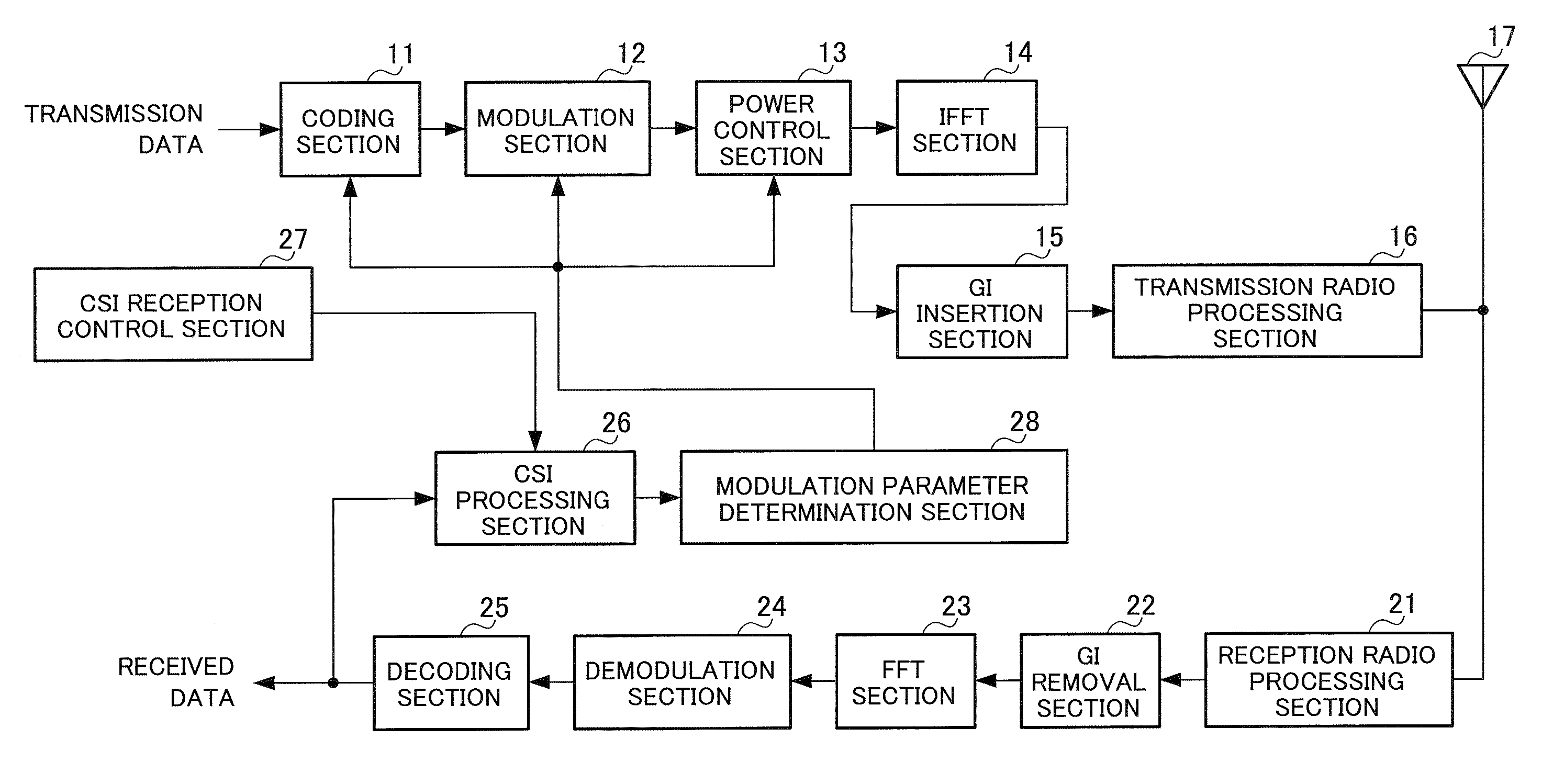
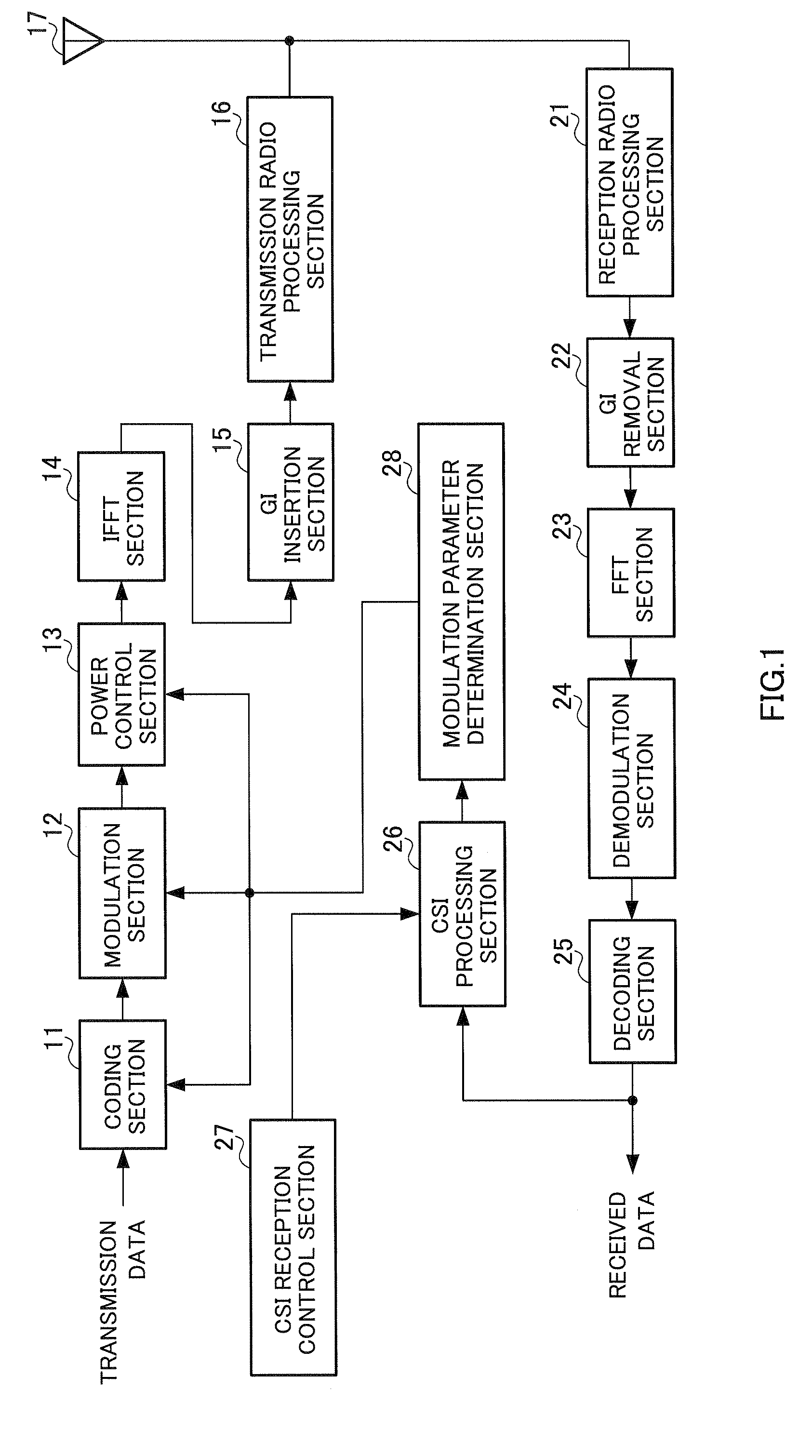
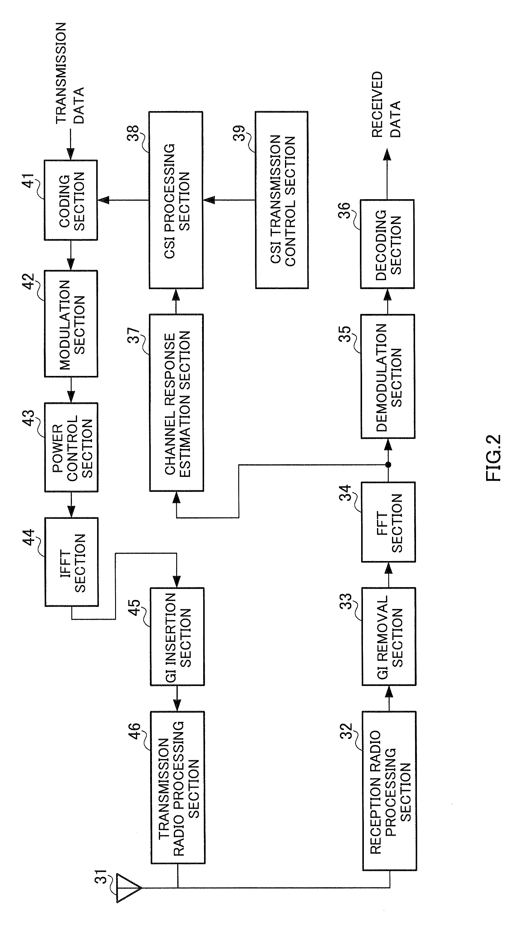
[0072] The radio communication apparatus shown in FIG. 1 is a CSI receiving-side radio communication apparatus, and the radio communication apparatus shown in FIG. 2 is a CSI transmitting-side radio communication apparatus. In the following description, a CSI receiving-side radio communication apparatus is referred to as a CSI receiving apparatus, and a CSI transmitting-side radio communication apparatus is referred to as a CSI transmitting apparatus. A CSI receiving apparatus transmits a multicarrier signal composed of a plurality of subcarriers to a CSI transmitting apparatus using modulation parameters (one or more of: channel coding method, channel coding rate, modulation method, transmission power) determined based on CSI. On the other hand, a CSI transmitting apparatus receives a multicarrier signal transmitted from a CSI receiving apparatus, and generates CSI based on a channel response value per subcarrier or per segment of the multicarrier signal. The above CSI receiving ap...

embodiment 2

[0136] A CSI transmitting apparatus according to this embodiment has a similar configuration to that of Embodiment 1, differing from Embodiment 1 in that an update timing signal is input to comparison result memory 385 only at the timing at which CSI of all of subcarriers 1 through 24 is fed back, and comparison results are not updated at other timings.

[0137] The operation of CSI frame generation section 386 according to this embodiment is described below. In this embodiment, CSI frame generation section 386 operates as shown in FIG. 15.

[0138] In FIG. 15, first, a generation timing signal is input to CSI frame generation section 386 from CSI transmission control section 39 at timing t3n. At the same time, an update timing signal is input to comparison result memory 385, and therefore the contents of comparison result memory 385 are updated with the comparison results newly obtained by comparison section 384. After updating, the contents of comparison result memory 385 are now assu...

embodiment 3

[0155] Most multipath channel environments are NLOS (Non line of sight) environments in which there is an obstruction between a transmitting station and a receiving station, and delayed waves are known to be subject to Rayleigh variation. When the delay time of a delayed wave is large relative to the symbol time, its characteristics have frequency selectivity. In this kind of frequency selective Rayleigh fading channel, cumulative probability distribution with respect to per-subcarrier SNR is as shown below.

[0156]FIG. 21 is a graph showing per-subcarrier SNR normalized cumulative probability distribution when average SNR=30 dB in a frequency selective Rayleigh fading channel. Reference number 601 indicates the cumulative probability distribution of SNR for all subcarriers, reference number 602 indicates the cumulative probability distribution of SNR of subcarriers for which the amount of variation per unit time is less than 1 dB, and reference number 603 indicates the cumulative pr...


PUM


Abstract

A wireless communication apparatus wherein the data amount of feedback information can be reduced, while a high throughput being maintained. In this apparatus, a CSI (Channel State Information) processing part (38) generates a CSI frame based on an SNR (Signal power to Noise power Ratio) for each of measured subcarriers, and a CSI transmission control part (39) generates a timing signal and control information required for generating the CSI frame, and controls the CSI processing part (38). The CSI processing part (38) generates a first frame (CSI1) which comprises the CSI of a subcarrier whose SNR variation amount is less than a threshold value, in a generation period that is greater than the generation period of a second frame (CSI2) comprising the CSI of a subcarrier whose SNR variation amount is equal to or greater than the threshold value.

Description

TECHNICAL FIELD [0001] The present invention relates to a radio communication apparatus and radio communication method. BACKGROUND ART [0002] In a fourth-generation or suchlike next-generation mobile communication systems, a data rate in excess of 100 Mbps is required even when moving at high speed. To meet this requirement, various kinds of radio communication using a bandwidth on the order of 100 MHz have been studied. Among these, a multicarrier transmission method represented by OFDM (Orthogonal Frequency Division Multiplexing) is considered to be particularly promising as a transmission method for next-generation mobile communication systems from the standpoints of adaptability to frequency selective fading environments and efficiency of frequency utilization. [0003] Heretofore, in order to achieve high throughput in a communication system that uses a multicarrier transmission method such as OFDM, a technology has been studied whereby the channel state per subcarrier, or per se...

Claims


Application Information

Patent Timeline
IPC IPC(8): H04B1/38
CPCH04L5/0007H04L5/006H04L5/0046H04L1/0026H04L27/2646
Inventor IMAMURA, DAICHINISHIO, AKIHIKO
Owner PANASONIC CORP
Why Eureka
Try Eureka