Silver layer formed by electrosilvering substrate material

a substrate material and silver layer technology, applied in the direction of layered products, transportation and packaging, chemistry apparatus and processes, etc., can solve the problems of practically impossible to strictly determine the quantity, maintain or manage the concentration of brightening agent in the plating bath, and achieve the effect of ensuring constant manufacturing quality and reducing the amount of brightening agent used

Inactive Publication Date: 2008-01-10
MATSUSHITA ELECTRIC WORKS LTD
View PDF8 Cites 28 Cited by
  • Summary
  • Abstract
  • Description
  • Claims
  • Application Information

AI Technical Summary

Benefits of technology

[0011]No brightening agent has to be added in the low-cyan bath. As measurement of a brightening agent concentration used for electroplating is impossible by a current analysis technology, it is practically impossible to strictly determine the quantity of, maintain or manage a brightening agent concentration in the plating bath. Thus, a plating bath containing no brightening agent can maintain constant manufacturing quality more easily.
[0012]A LED mounted substrate may be manufactured by ...

Problems solved by technology

As measurement of a brightening agent concentration used for electroplating is impossible by a current analysis technology, it is...

Method used


Image

  • Silver layer formed by electrosilvering substrate material
  • Silver layer formed by electrosilvering substrate material
  • Silver layer formed by electrosilvering substrate material

Examples


example 1

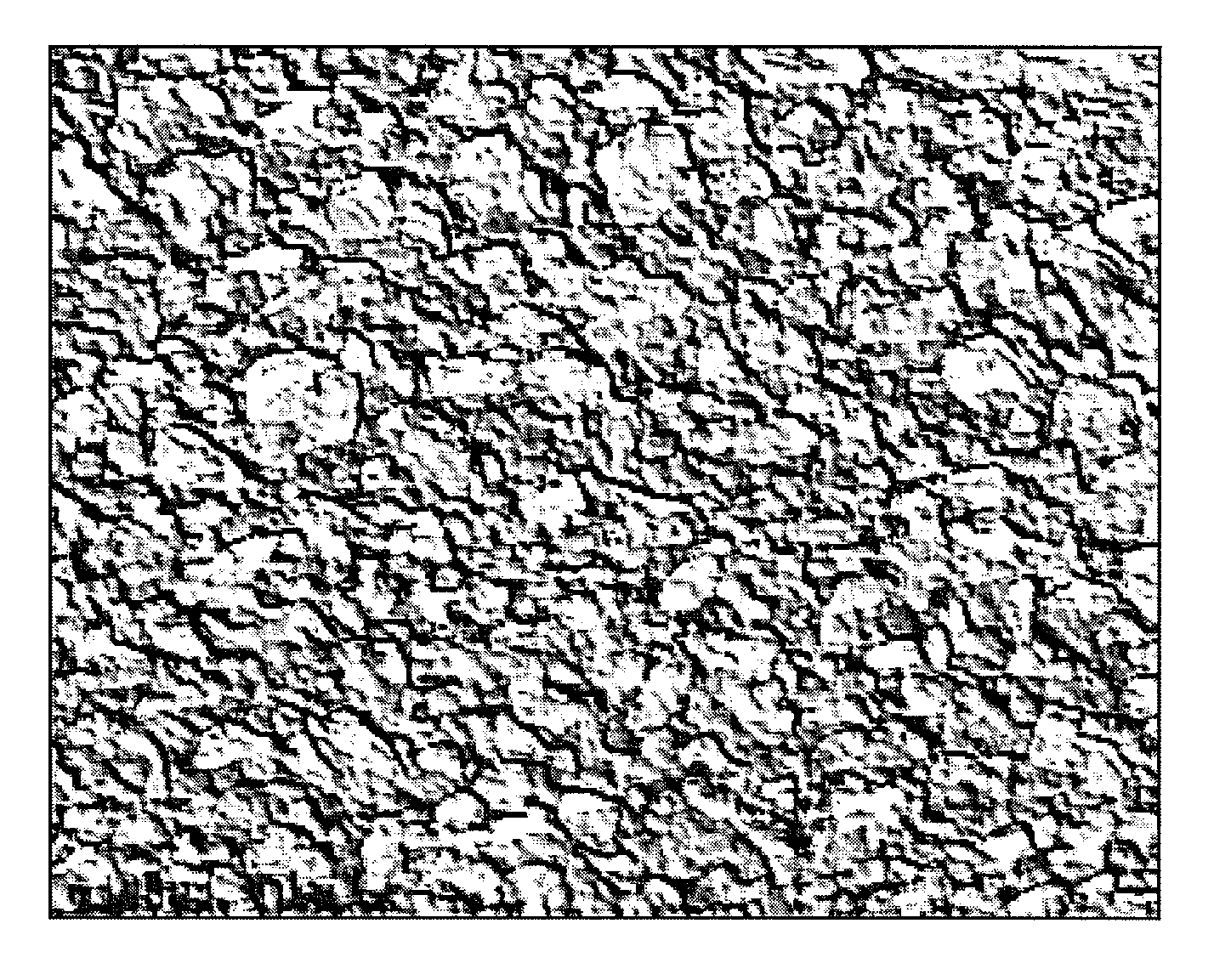
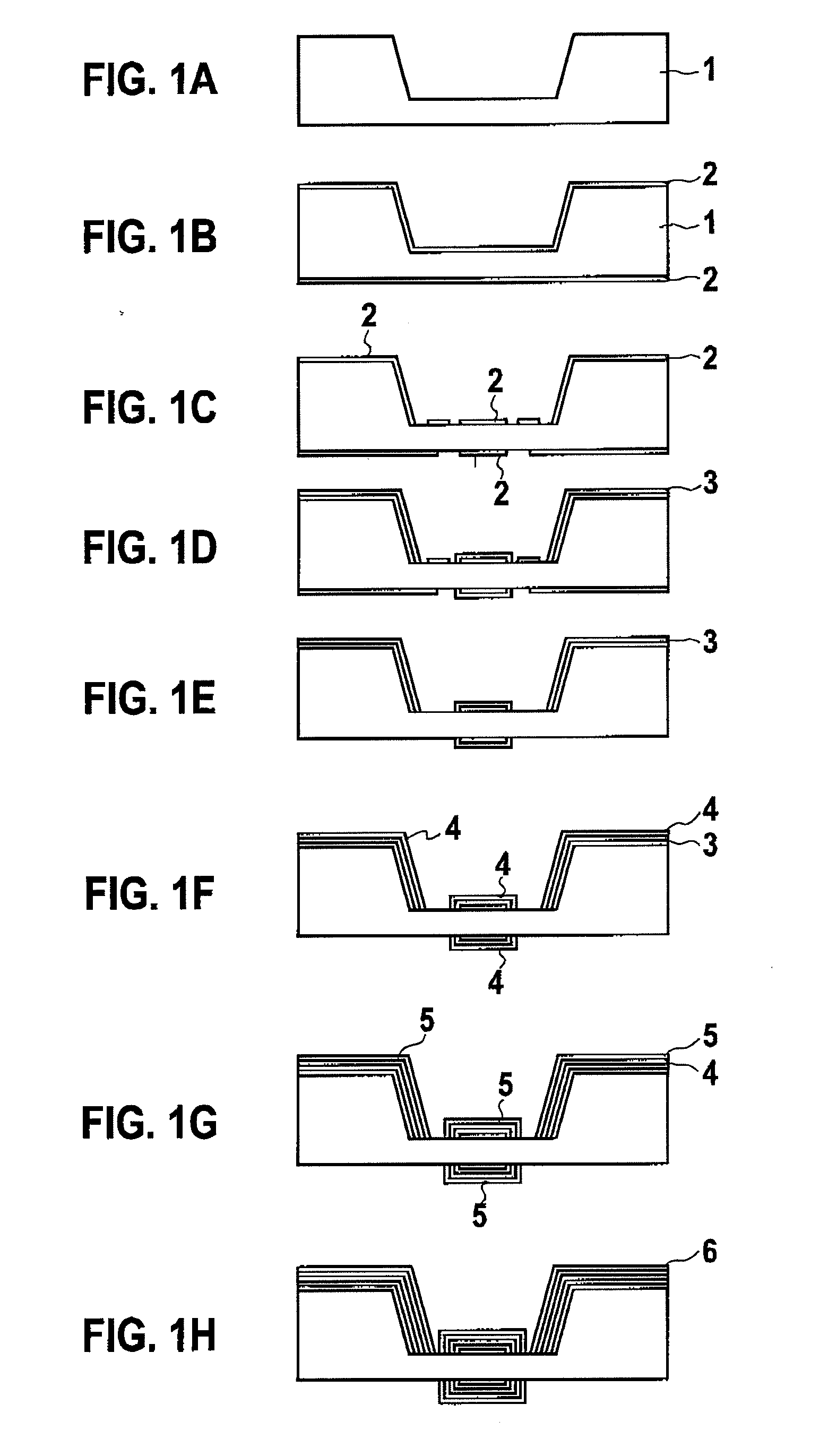
[0029]According to the Example 1, first, an alumina substrate of a flat plate shape (30×40×1.5 mm) was prepared. The substrate was dipped in a copper sulfate bath of a copper sulfate / pentahydrate concentration of 110 g / l, a sulfuric acid concentration 180 g / l and a chlorine ion concentration of 50 mg / l. The substrate was subjected to electric copper plating at a temperature of 22° C. for 136 seconds by setting current density to 2 A / dm2 to form a copper plated layer with a film thickness of 10 μm on a substrate surface. Then, the substrate was dipped in a low (concentration) cyan bath of a silver concentration of 65 g / l, a free cyanide concentration of 2 g / l, and a brightening agent concentration of 10 ml / l. The substrate was subjected to electrosilvering at a temperature 30° C. for 95 seconds by setting a current density to 2 A / dm2 to obtain a silver plated layer of the Example 1 with a film thickness of 2 μm on the copper plated layer.

example 2

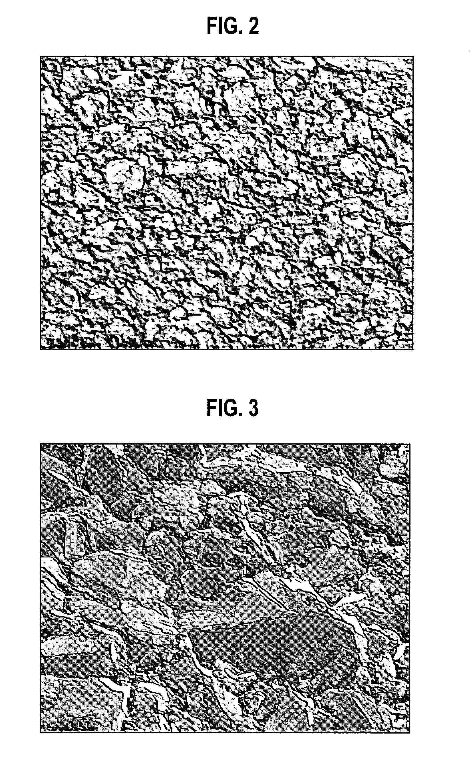
[0030]According to the Example 2, a substrate was dipped in a low cyan bath of a silver concentration of 65 g / l, a free cyanide concentration 2 g / l and a brightening agent concentration of 0 ml / l. The substrate was subjected to electrosilvering at a temperature 30° C. for 750 seconds by setting a current density to 2 A / dm2 to obtain a silver plated layer of the Example 2 with a film thickness of 16 μm on the copper plated layer.

example 3

[0031]According to the Example 3, a substrate was dipped in a low cyan bath of a silver concentration of 65 g / l, a free cyanide concentration of 2 g / l, and a brightening agent concentration of 0 ml / l. The substrate was subjected to electrosilvering at a temperature 60° C. for 190 seconds by setting a current density to 2 A / dm2 to obtain a silver plated layer of the Example 3 with a film thickness of 4 μm on the copper plated layer.


PUM

PropertyMeasurementUnit
Grain sizeaaaaaaaaaa
Temperatureaaaaaaaaaa

Abstract

The inventors have conducted vigorous studies, and discovered as a result that it is possible to form a silver layer having a high reflectance of about 90 to 99% in a visible light are a by setting a grain size of an outermost surface of a silver plated layer within a range of 0.5 μm or more to 30 μm or less.

Description

CROSS REFERENCE TO RELATED APPLICATION[0001]This application is based upon and claims the benefit of priority from a Japanese Patent Application No. TOKUGAN 2006-187053, filed on Jul. 6, 2006; the entire contents of which are incorporated herein by reference.BACKGROUND OF THE INVENTION[0002]1. Field of the Invention[0003]The present invention relates to a silver layer formed by electrosilvering a substrate material.[0004]2. Description of the Related Art[0005]The silver layer has a high light reflectance (abbreviated to reflectance herein after), and thus it has widely been used for a reflecting plate of downlight illumination or a reflective surface of a light emitting diode (LED) package. In the case of the LED package, as a current input to the LED is increased until a predetermined light output is obtained, a life of the LED is greatly affected. Accordingly, in a high-output LED package applied for house illumination or main illumination of an automobile headlight or the like, s...

Claims


Application Information

Patent Timeline
IPC IPC(8): H01L23/58H01L33/60C25D5/10C25D5/54C25D7/00H01L33/00
CPCC25D3/46C25D5/02C25D5/10Y10T428/12882H01L33/60Y10T428/12993Y10T428/12896C25D5/50C25D5/617C25D5/627
Inventor NAKAHARA, YOUICHIROIKEGAWA, NAOTO
Owner MATSUSHITA ELECTRIC WORKS LTD
Why Eureka
Try Eureka