Optical methods and systems in marine seismic surveying

a technology of optical methods and systems, applied in seismology, seismology, instruments, etc., can solve the problem of not offering a stable mounting platform, and achieve the effect of reducing or eliminating lens distortion

Inactive Publication Date: 2008-01-10
WESTERNGECO LLC
View PDF58 Cites 39 Cited by
  • Summary
  • Abstract
  • Description
  • Claims
  • Application Information

AI Technical Summary

Benefits of technology

[0010] In certain embodiments, water may contain small air bubbles that will disperse the light so that the rays do not hit the intended targets. Methods of the invention include those wherein the size of the beams and / or means for reflection are adjustable so that a light ray passing a few millimeters to the side of the bubble will still hit the intended target and make a measurement possible.
[0011] In certain embodiments, advantage is taken of the fact that lasers may exhibit very fast measurement cycles, and measurements may be taken virtually continuously, even during firing of source elements. At some time after a source element is triggered, the measurements may fail, for instance when using air-guns the water will be filled with air bubbles. Of course, in the case of seismic sources, the geometry sought is the one representative at the moment the source elements fire. The fast measurement rate of lasers makes it possible to select the data set taken closest to the time of firing and make a network solution from that. The rest of the data may then be discarded. The calculation may comprise computing a network, and this may include one or more computers to receive the measured ranges and process the data using an appropriate algorithm. If the computer has capacity and there is a desire to track a spread component between seismic shots it is of course within the invention to also compute updates more frequently.
[0017] Methods in accordance with the invention include measuring image coordinates of one and the same point or mark on a spread element in two images exposed at two different locations. This makes it possible to determine the 3D coordinates of the point in a stereographic model. Repeating this process for a multitude of points makes it possible to determine their relative positions. As the number of points increases the stereographic model becomes closer to a three-dimensional image of the spread component. If the spread component was stationary one could just move the camera around and take the snapshots at different times. When the position and shape change with time it may be necessary to use two cameras to take the two pictures simultaneously.
[0018] Other methods of the invention include calibrating the cameras to reduce or eliminate distortions of the lenses, deviation of the projection surface from a plane, and other effects affecting the image coordinates. Given this information the errors can be compensated for. Thus, other inventive methods comprise determining shape of a spread component using calibrated cameras, and optionally obtaining the size (scale) of the spread component using a known baseline distance, which may be selected from a distance between the two cameras, a known distance between two marks on the spread component, or a measured distance, for instance the distance from the camera to a mark on a spread element.
[0021] The quality of the images may be an issue for a successful process. In daylight conditions and clear water it may be possible to take the snapshots without adding any light. Methods of the invention include enhancing contrast in the images using artificial lights to ease identification of the correct marks. The artificial lights could for instance be obtained from an ordinary flash. A better approach may be to position lights in place of the marks on the spread elements. Where a flash is employed, one or more light reflectors may be used.
[0024] Yet other methods of the invention comprise duplicating the system used for the third aspect, making possible to do all the three methods. This may be a further advantage in a difficult environment, as it would give superb redundancy within the system. The methods would then be far more tolerant to failed or false measurements.

Problems solved by technology

The typical embodiment of a marine seismic source does not offer any stable mounting platform where correct pointing direction could be ensured.

Method used


Image

  • Optical methods and systems in marine seismic surveying
  • Optical methods and systems in marine seismic surveying
  • Optical methods and systems in marine seismic surveying

Examples


embodiment 100

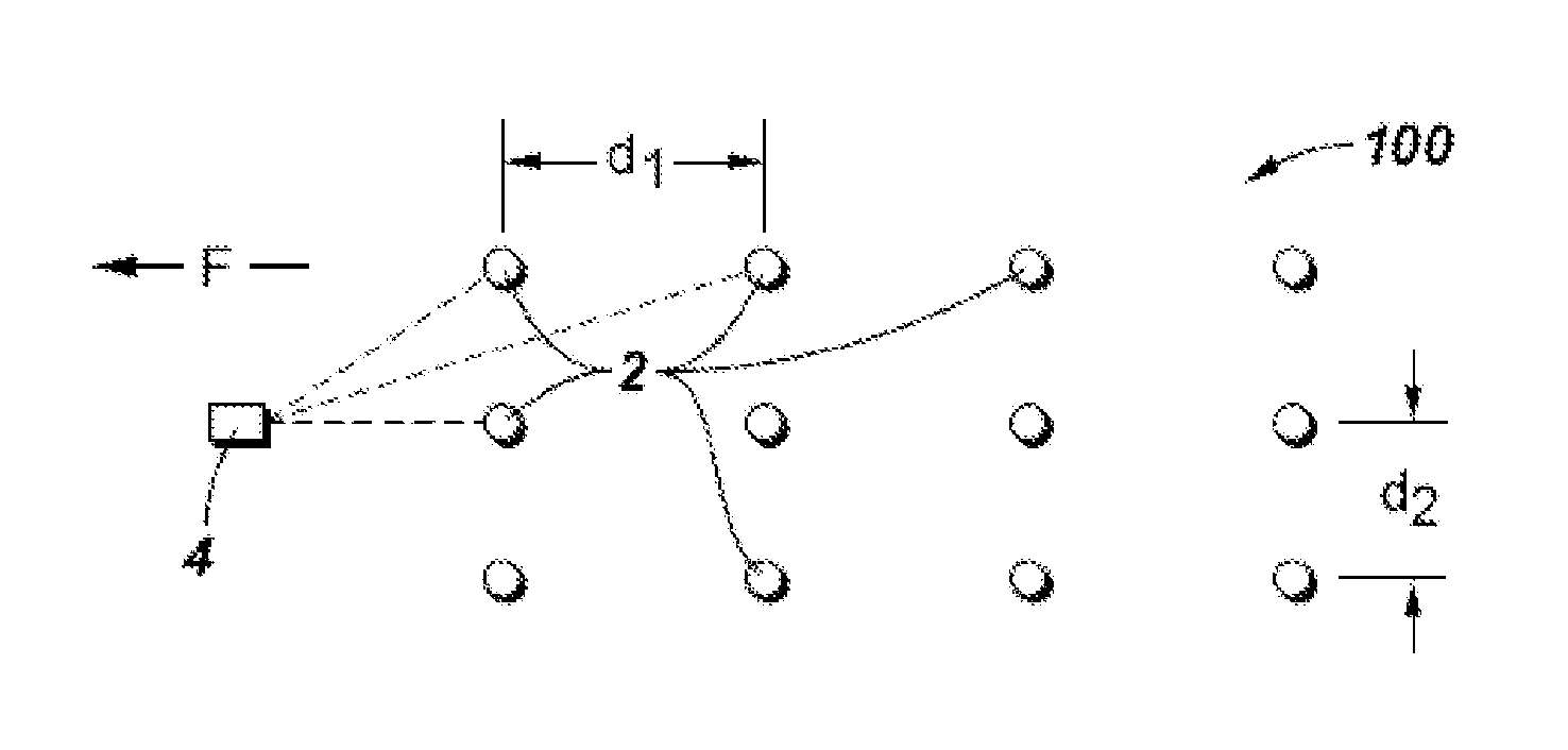
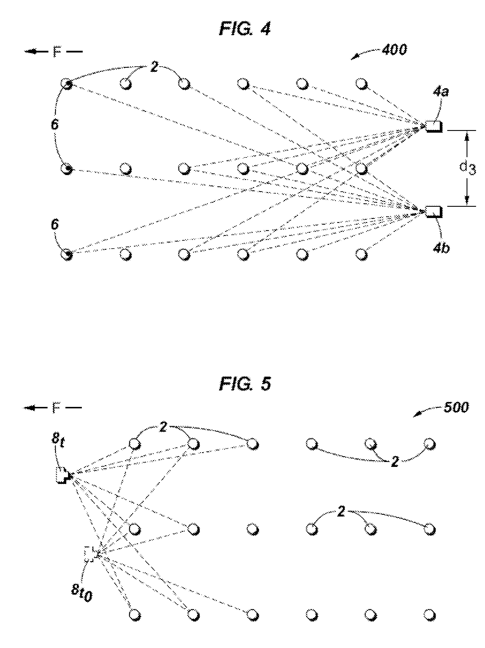
[0040] Referring now to the figures, FIGS. 1-8, inclusive, are highly schematic plan view illustrations, not to scale, of eight non-limiting embodiments of the invention. The same reference numerals are used throughout the various figures to point out the same or similar features, and each figure includes a direction arrow “F” indicating the direction of flow or travel of the particular spread component or spread elements illustrated. FIGS. 1-4 illustrate four embodiments of the invention using laser ranging. Arguably, the most accurate way of distance measurement available today using light is the approach used in electronic distance measurement (EDM) devices. This approach depends to some extent on a continuous signal while measuring although some interruptions are tolerated. A common way of measuring distance using a laser is to send pulses and measure the time delay of the reflected signal. In either case it depends on a beam pointing directly on the reflector or the reflective ...

embodiment 200

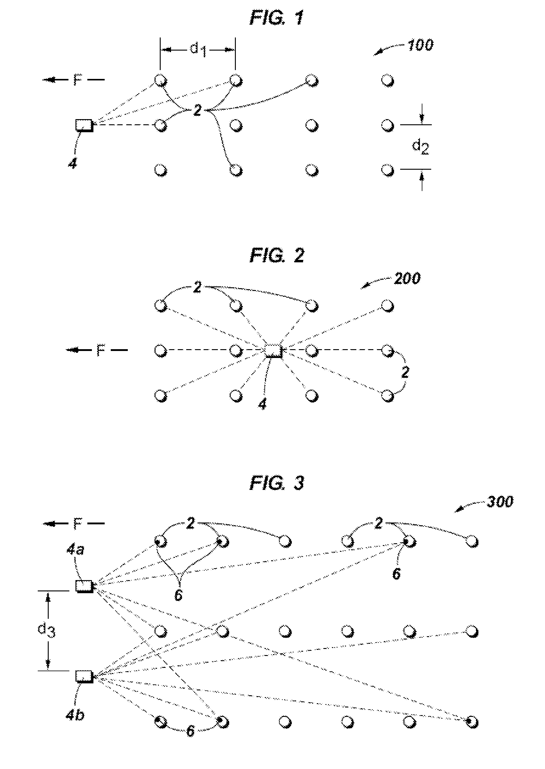
[0041] The typical embodiment of a marine seismic source may not offer a stable mounting platform where correct pointing direction of an optical device such as laser 4 could be ensured. This problem may be solved using an optical scanner, in some embodiments a laser scanner. One way of making a laser scanner is to supply a rotating mirror or a prism that bends the light ray so that each light pulse is sent in a different angle forming a fan of light pulses. Using a second mirror or prism it is possible to direct the light pulses in a spherical sector large enough to ensure that there is a pulse hitting each spread element 2. Such an embodiment 200 is illustrated schematically in FIG. 2, where laser 4 is converted into a laser scanner by use of such optical techniques. As illustrated in FIG. 2 by dashed lines, laser scanner 4 may scan all source elements 2 and calculate distances indicated by the dashed lines, enabling a more accurate estimate of position of all source elements 2. Op...

embodiment 700

[0054] The quality of the images may be an issue for a successful process. In daylight conditions and clear water it may be possible to take the snapshots without adding any light. If there is sufficient light to obtain good contrast in the images nothing more is needed to complete the data acquisition. The contrast may be improved by applying artificial light in various forms, such as attaching lights 12 to appropriate places on one or more spread elements. Methods of the invention include enhancing contrast in the images using artificial lights to ease identification of the correct marks. The artificial lights could for instance be obtained from an ordinary flash. A better approach may be to position lights in place of the marks on the spread elements. Optional methods include adjusting the intensity to maximise the contrast under the given conditions, and using monochromatic light sources of different color or wavelength to help identify the marks in the images and distinguish th...


PUM


Abstract

Methods and systems for determining position of marine seismic spread components are disclosed. One method comprises exposing an underwater marine seismic spread component to an optical device, and calculating geometry of the spread component using at least some of the data obtained by the optical device, for example travel time for an optical signal to travel to and return from one or more spread elements in the spread component. The optical device may comprise one or more laser scanners, cameras, or laser scanners and cameras. The spread component may be a marine seismic source, a marine seismic streamer cable, and the like. This abstract allows a searcher or other reader to quickly ascertain the subject matter of the disclosure. It will not be used to interpret or limit the scope or meaning of the claims. 37 CFR 1.72(b).

Description

BACKGROUND OF THE INVENTION [0001] 1. Field of Invention [0002] The present invention relates generally to the field of marine seismic surveying, and more specifically to using optics to more accurately quantify marine seismic data. [0003] 2. Related Art [0004] Marine seismic exploration investigates and maps the structure and character of subsurface geological formations underlying a body of water. In one common arrangement, a seismic spread comprises one or more streamer cables containing acoustic seismic receivers deployed into the water behind a tow vessel, and one or more acoustic seismic sources may be towed by the same or different vessel. Less than perfect knowledge of the actual positions of the source elements at the time of firing and receivers at the time of arrival of reflected seismic waves may result in less than acceptable seismic data. SUMMARY OF THE INVENTION [0005] In accordance with the present invention, optical methods and systems are described to determine geo...

Claims


Application Information

Patent Timeline
Patent Type & Authority Applications(United States)
IPC IPC(8): G01V1/38
CPCG01V1/3835
Inventor VIGEN, ERIKYANG, LUREN
Owner WESTERNGECO LLC
Why Eureka
Try Eureka