Staged hydrocarbon reformer

Inactive Publication Date: 2008-01-10
DELPHI TECH INC
View PDF4 Cites 3 Cited by
  • Summary
  • Abstract
  • Description
  • Claims
  • Application Information

AI Technical Summary

Benefits of technology

[0012] Briefly described, a hydrocarbon reformer in accordance with the invention comprises a plurality of sequential reforming stages that may or may not be separated by non-reforming mixing spaces therebetween. Each of the stages may reside inside a common housing. The entire reformer is a heat exchange reformer wherein it adds heat to endothermic reactions and removes heat from exothermic reactions, as needed, to prevent carbon build-up, coking and substrate / bed degradation.
[0013] The first reforming stage, is arranged to have relatively low catalytic activity, to minimize heat buildup during CPOx exothermic catalysis. This may be achieved by having a relatively short residence time, governed by geometric constraints, and / or relatively low catalytic capability, governed by catalyst loading constraints, such that not all of the fuel and air passing through the first stage is catalyzed, thereby preventing thermal excess in the first stage and consequent bed erosion. Preferably, this stage reacts about one-quarter of the fuel. The fast exothermic combustion reaction near the front edge of the catalyst produces largely water and carbon dioxide, but little hydrogen, while consuming some of the hydrocarbon and oxygen. The endothermic reactions in the subsequent stages reduce hydrogen and carbon monoxide while consuming water, carbon dioxide, and the remaining hydrocarbon fuel and oxygen in a combination of steam- and dry-reforming processes.
[0014] In a second stage following the first stage in series, the activity of the catalytic material is increased as are the length of the stage and residence time of the reactants.

Problems solved by technology

During the endothermic reforming mode, the amount of molecular oxygen available to the reformer has been reduced so that the temperature of the leading edge of the reformer can only heat the fuel mixture from its initial 150 C to about 500 C. This temperature is too low for complete endothermic reforming to occur at the leading edge of the reformer resulting in local precipitation of carbon and then coking during further temperature spikes.
A serious problem for prior art catalyst beds is that intense exothermic catalysis and / or combustion occurs at the leading edge of the bed, during certain exothermic modes of operation, where the concentration of reactants entering the reformer is highest and the dispersal of heat is lowest, causing rapid heat release and heat buildup resulting in unacceptably elevated substrate, washcoat, and catalyst temperatures along the leading edge.
During sustained use of the reformer, the catalyst bed is progressively eroded, ablated, or otherwise thermally deactivated along the leading edge, resulting in a progressively smaller bed and eventual failure of the reformer.
It is difficult to remove heat from the front edges of a prior art catalyst and substrate to control the exothermic reactions, which area dominates but a small part geometrically of a reformer.
This leads to a major problem in design, durability, and performance of prior art reformers.

Method used


Image

  • Staged hydrocarbon reformer
  • Staged hydrocarbon reformer
  • Staged hydrocarbon reformer

Examples


Embodiment Construction

[0034] The distinctions and benefits of the present invention may be better appreciated by first considering the elements and limitations of a prior art catalytic reformer.

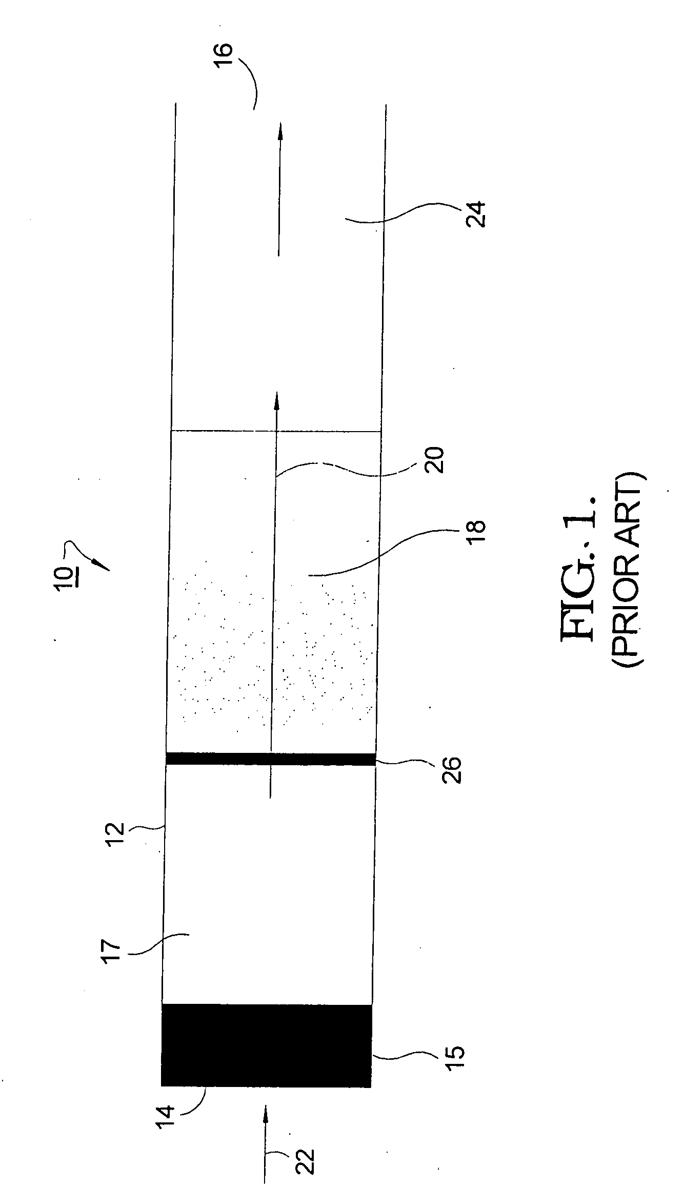
[0035] Referring to FIGS. 1 through 5, a prior art hydrocarbon catalytic reformer 10 includes a housing 12 having an inlet 14 and outlet 16. Disposed within housing 12 is a catalyst bed 18 having porosity in at least a longitudinal direction 20. Bed 18 typically includes a durable non-catalytic substrate coated with a washcoat including or supporting catalytic means. The substrate is formed typically of either a metal or a ceramic, as discussed further below. Conventional means for controlling overall temperature, fuel flow rate, air flow rate, and the like are assumed but not shown in FIG. 1.

[0036] In operation, a mixture 22 of hydrocarbon and oxygen, typically in the form of air, is introduced into reformer 10 through inlet 14 and thence through a mixture preparation unit 15 and fluid mixing zone 17. The mixtu...


PUM


Abstract

A hydrocarbon reformer comprising a plurality of sequential reforming stages. The first stage has relatively low catalytic activity to minimize heat buildup in exothermic catalysis, which may be achieved by having a short residence time and / or relatively low catalytic capability, such that not all of the fuel and air passing through the first stage is catalyzed, thereby preventing thermal excess in the first stage and consequent bed erosion. Exothermic combustion near the front edge of the reformer produces water and carbon dioxide, but little hydrogen, while consuming some of the hydrocarbon and oxygen. Endothermic reactions in the following stages produce hydrogen and carbon monoxide while consuming the remaining hydrocarbon fuel and oxygen in a combination of steam- and dry-reforming processes. In each succeeding stage, the catalytic capability is increased as are the length of the stage and residence time of the reactants.

Description

RELATIONSHIP TO OTHER APPLICATIONS AND PATENTS [0001] The present application is a Continuation-In-Part of a pending U.S. patent application Ser. No. 11 / 395,672, filed Mar. 31, 2006.TECHNICAL FIELD [0002] The present invention relates to hydrocarbon reformers for producing hydrogen-rich fuel for fuel cells; more particularly, to such a reformer comprising a plurality of sequential reforming stages; and most particularly, to a staged reformer system supporting both exothermic and endothermic reforming wherein reforming is controlled and limited in sequential stages to prevent thermal degradation of the reformer and provide high-efficiency reforming of the hydrocarbon fuel. BACKGROUND OF THE INVENTION [0003] Fuel reformers are well known in the art as devices for converting hydrocarbons to reformate containing hydrogen (H2) and carbon monoxide (CO) as fuel for fuel cell systems, and especially for solid oxide fuel cell (SOFC) systems. A type of fuel reformer used in such an applicatio...

Claims


Application Information

Patent Timeline
IPC IPC(8): B01J10/00
CPCB01J15/005B01J19/2485B01J19/249B01J2219/00117B01J2219/2453B01J2219/2454C01B2203/143B01J2219/2479C01B3/382C01B2203/0227C01B2203/0261C01B2203/1047C01B2203/142B01J2219/2459
Inventor FISCHER, BERNHARD A.
Owner DELPHI TECH INC
Why Eureka
Try Eureka