Variable valve actuating apparatus for internal combustion engine
a technology of variable valves and actuating devices, which is applied in the direction of valve arrangements, machines/engines, output power, etc., can solve the problems of limited improvement in engine starting performance, and achieve the effect of improving the startability or starting performance of an engine more reliably and improving the startability or starting performance of an engin
- Summary
- Abstract
- Description
- Claims
- Application Information
AI Technical Summary
Benefits of technology
Problems solved by technology
Method used
Image
Examples
first embodiment
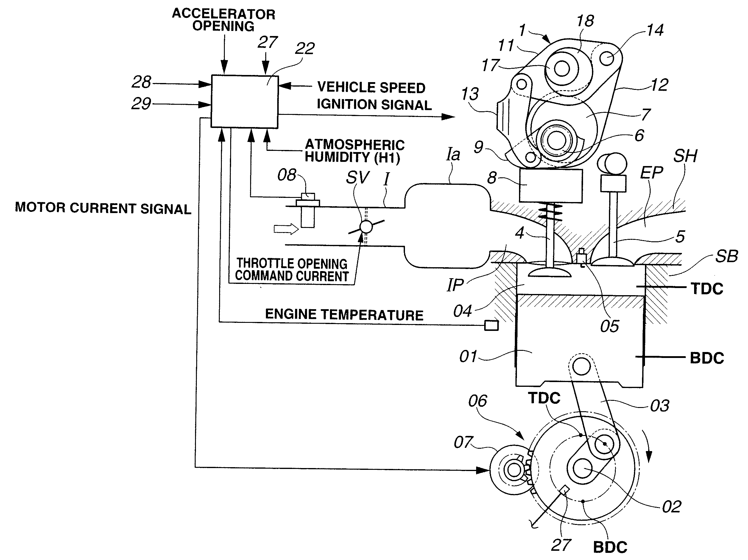
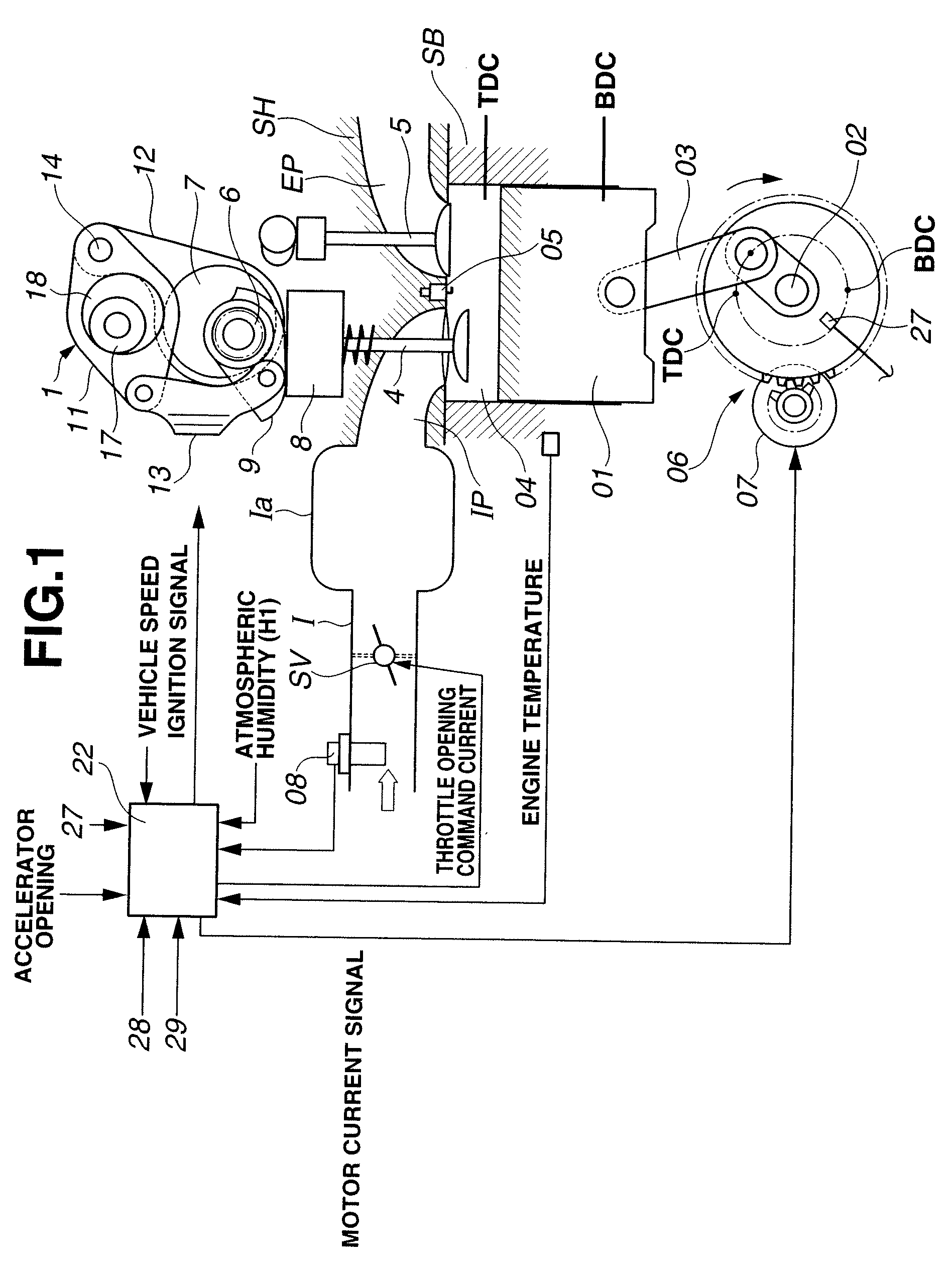
[0031]FIG. 1 schematically shows an engine system including a variable valve actuating system or apparatus according to the present invention. In this embodiment, the internal combustion engine is a four-cycle multi-cylinder internal combustion engine, and the variable valve actuating system is applied to the intake valve's side.
[0032]A cylinder bore shown in FIG. 1 is formed in a cylinder block SB of the engine. A piston 01 is received in this cylinder bore so that piston 01 can slide up and down in the cylinder bore. Intake and exhaust ports IP and EP are formed in a cylinder head SH. For each cylinder, there are provided a pair of intake valves 4, and a pair of exhaust valves 5 for opening and closing the respective open ends of the intake and exhaust ports. Piston 01 is connected with a crankshaft 02 through a connecting rod 03. A combustion chamber 04 is formed between the crown of piston 01 and a lower surface of cylinder head SH.
[0033]In an intake passage I on the upstream si...
second embodiment
[0086]In the second embodiment, the starter motor 07 shown in FIG. 1 is constructed to rotate in a forward direction and a reverse direction. With this starter motor 07 of the reversible type, the variable valve actuating system can adjust the crank angle phase of crank shaft 02 even in an engine stop state or in a very low engine speed state just before a stop of the engine.
[0087]FIG. 8 show a control process performed by controller 22 according to the second embodiment.
[0088]At a step S21, controller 22 examines whether the ignition key switch is on or not. When the ignition key switch is not on, controller 22 proceeds directly to the end of the process of FIG. 8 since the engine is in the stop state. When the ignition key switch is on, controller 22 proceeds to a step S22.
[0089]At step S22, controller 22 detects a current engine operating state by reading signals on information including the current crank angle from crank angle sensor 27, the engine temperature (or engine coolant...
fourth embodiment
[0120]In the fourth embodiment, the variable valve actuating system is arranged to detect the actual crank angle at the time of engine stop instead of the timing immediately before a start of the engine. Therefore, the system can reduce the time required to start the engine by eliminating the need for detecting the crank angle at the time of start.
[0121]In the fourth embodiment, since the crank shaft 02 is rotating slightly at the time of detection of the crank angle, the system can employ, as the crank angle sensor, a trigger type sensor capable of sensing at time intervals during rotation, instead of a costly absolute angle sensor.
[0122]The present invention is not limited to the first through fourth embodiments. The present invention is applicable not only to the intake side, but to the exhaust side as well. Moreover, the present invention is applicable simultaneously to both sides. When the variable valve actuating mechanism is provided on the exhaust side, the variable valve ac...
PUM
 Abstract
Description
Claims
Application Information
 - R&D
- Intellectual Property
- Life Sciences
- Materials
- Tech Scout
- Unparalleled Data Quality
- Higher Quality Content
- 60% Fewer Hallucinations
Browse by: Latest US Patents, China's latest patents, Technical Efficacy Thesaurus, Application Domain, Technology Topic, Popular Technical Reports.
© 2025 PatSnap. All rights reserved.Legal|Privacy policy|Modern Slavery Act Transparency Statement|Sitemap|About US| Contact US: help@patsnap.com


