Exhaust gas heat exchanger
a heat exchanger and exhaust gas technology, applied in the direction of machines/engines, lighting and heating apparatus, laminated elements, etc., can solve the problems of pressure loss of exhaust gas flowing in the tube and the restriction of the hydraulic resistance of cooling fluid (such as cooling water), and achieve the effect of improving performan
- Summary
- Abstract
- Description
- Claims
- Application Information
AI Technical Summary
Benefits of technology
Problems solved by technology
Method used
Image
Examples
embodiments
First Embodiment
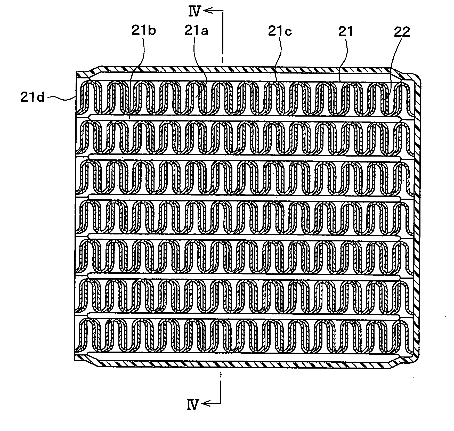
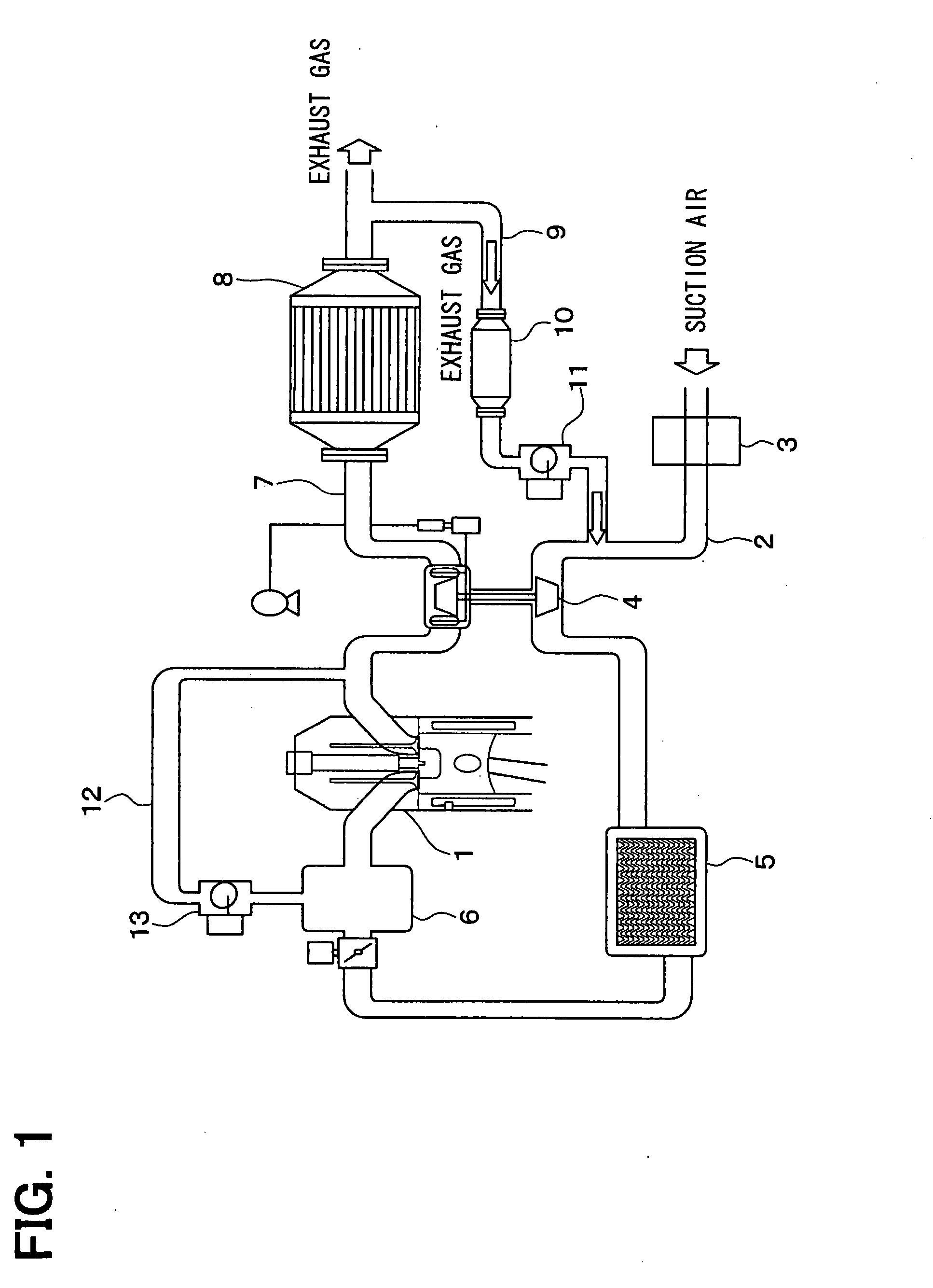
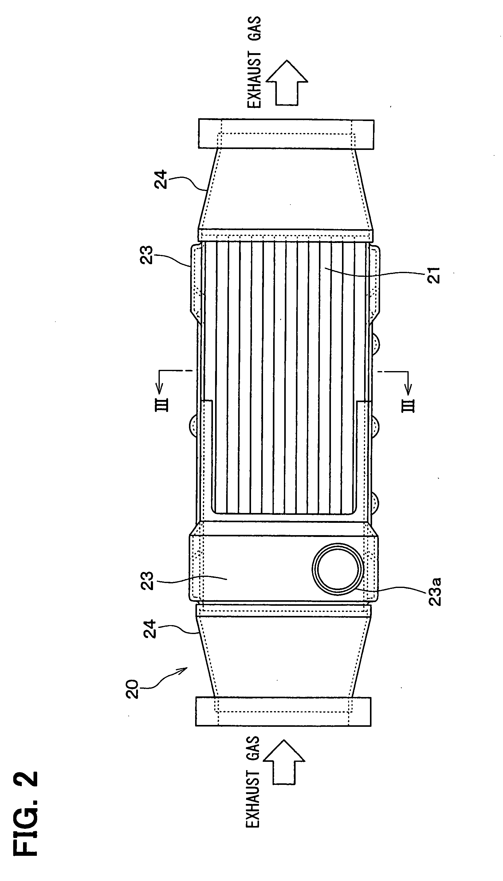
[0042]An exhaust gas heat exchanger according to a first embodiment of the present invention will be described with reference to FIGS. 1-8. The exhaust gas heat exchanger can be suitably used as an exhaust gas recirculation cooler 10 (EGR cooler), for example.
[0043]As shown in FIG. 1, the EGR cooler 10 can be provided for an exhaust gas recirculation device. The exhaust gas recirculation device has, for example, an air cleaner 3, a variable tube actuator 4, an inter cooler 5 and an intake manifold 6 which are arranged at a halfway portion of an air suction passage 2 of an engine 1.
[0044]The tube actuator 4 and a DPF 8 (diesel particulate filter) are arranged at a half portion of an exhaust passage 7 of the engine 1. A first exhaust gas recirculation pipe 9 is connected with a downstream side of exhaust gas of the DPF 8 and an upstream side of suction air of the tube actuator 4. The EGR cooler 10 and an exhaust gas recirculation valve 11 (EGR valve) are arranged at a ...
second embodiment
[0076]According to a second embodiment of the present invention, the optimum specifications of the inner fin 22 are determined according to different criterions and parameters from those of the above-described first embodiment.
[0077]In the second embodiment, the optimum specifications of the inner fin 22 are determined based on the relation between an equivalent circle diameter de and an EGR gas density ratio ρ.
[0078]In this case, as shown in FIG. 6, the equivalent circle diameter de means a diameter of an equivalent circle into which the field C in the cross section (substantially perpendicular to exhaust gas flowing direction) of the inner fin 22 is converted. The field C is positioned between the convex portions 31 which are arranged at the crest positions (or trough positions) and adjacent to each other, and surrounded by the inner fin 22 and the tube 21. The equivalent circle diameter de can be calculated by the following formula (2).
de=4×S / W (2)
[0079]S represents an area (whi...
third embodiment
[0093]According to a third embodiment of the present invention, the optimum specifications of the inner fin 22 are determined according to different criterions and parameters from those of the above-described embodiments.
[0094]In the third embodiment, the optimum specifications of the inner fin 22 are determined based on the relation between the segment length L and the EGR gas density ratio (ρ ratio).
[0095]FIG. 11 shows the relation between the segment length L and the EGR gas density ratio (ρ ratio), which is a ratio when the maximum value of the EGR gas density ρ is set as 100%. The relation shown in FIG. 11 is obtained with the same condition as that of FIG. 10, excepting the fin height fh and the segment length L.
[0096]The curve F in FIG. 11 is calculated when fh<7 and fp≦5, for example, when fh is equal to 4.6 and fp is equal to 4.5. Thus, when the segment length L is in the range of 0.5
PUM
 Abstract
Description
Claims
Application Information
 - R&D
- Intellectual Property
- Life Sciences
- Materials
- Tech Scout
- Unparalleled Data Quality
- Higher Quality Content
- 60% Fewer Hallucinations
Browse by: Latest US Patents, China's latest patents, Technical Efficacy Thesaurus, Application Domain, Technology Topic, Popular Technical Reports.
© 2025 PatSnap. All rights reserved.Legal|Privacy policy|Modern Slavery Act Transparency Statement|Sitemap|About US| Contact US: help@patsnap.com


