
Rapid Microfluidic Assay for Quantitative Measurement of Interactions Among One or More Analytes

a microfluidic and quantitative measurement technology, applied in the field of microfluidic competitive assay devices and assay methods, can solve the problems of adding additional reagent costs and labor, and achieve the effect of rapid quantitative measurement of interactions

Inactive Publication Date: 2008-01-17
UNIV OF WASHINGTON
View PDF5 Cites 41 Cited by
  • Summary
  • Abstract
  • Description
  • Claims
  • Application Information

AI Technical Summary

Benefits of technology

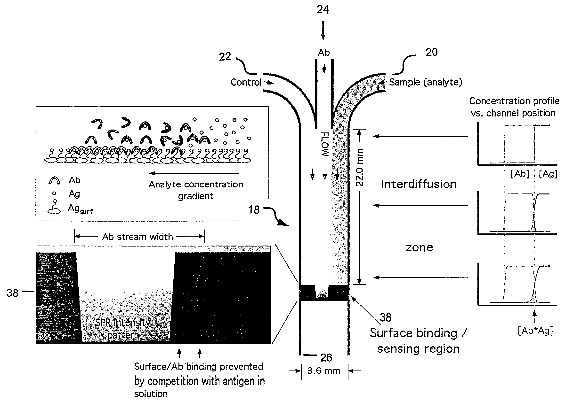
[0006] The present invention provides microfluidic competitive assay devices and assay methods for rapid, quantitative measurement of interactions between an analyte and its binding partner that is immobilized on a sensing surface of the microfluidic assay device.
[0008] The methods of the present invention provide an improvement over conventional competitive immunoassays because quantitative determinations of multiple analytes in a single small fluid sample (e.g., <0.1 mL) can be made rapidly and simultaneously with a reference solution. Additionally, the methods of the present invention do not require the addition of a labeled component to the sample prior to measurement. Moreover, by selecting particular fluidic geometries of the microfluidic competitive immunoassay device, the measurements can include real-time comparisons to reference solutions to control for variations in temperature, detector response, and other manufacturing uncertainties. These controls can be done simultaneously with the sample measurement and therefore do not increase the time required to conduct the assay.
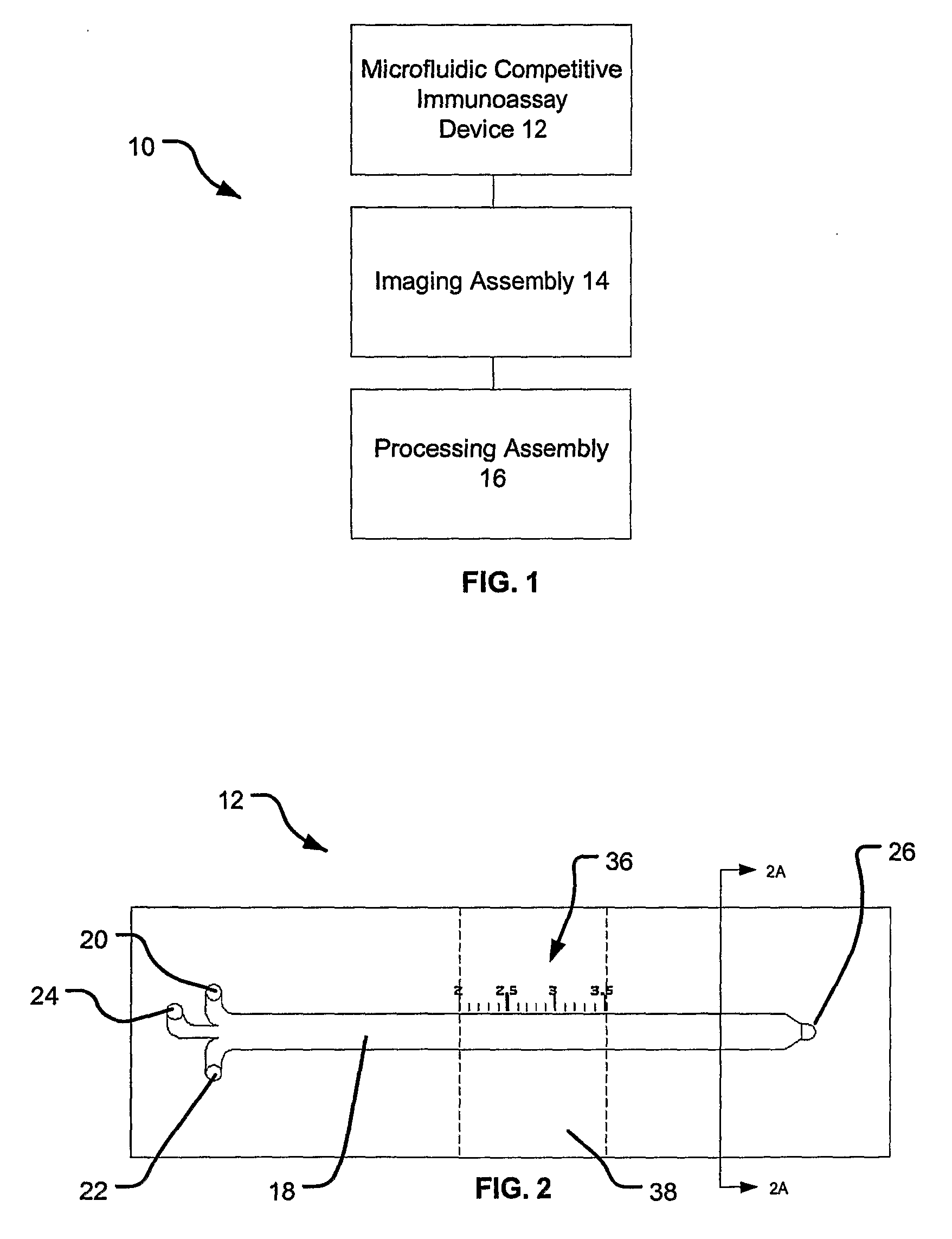
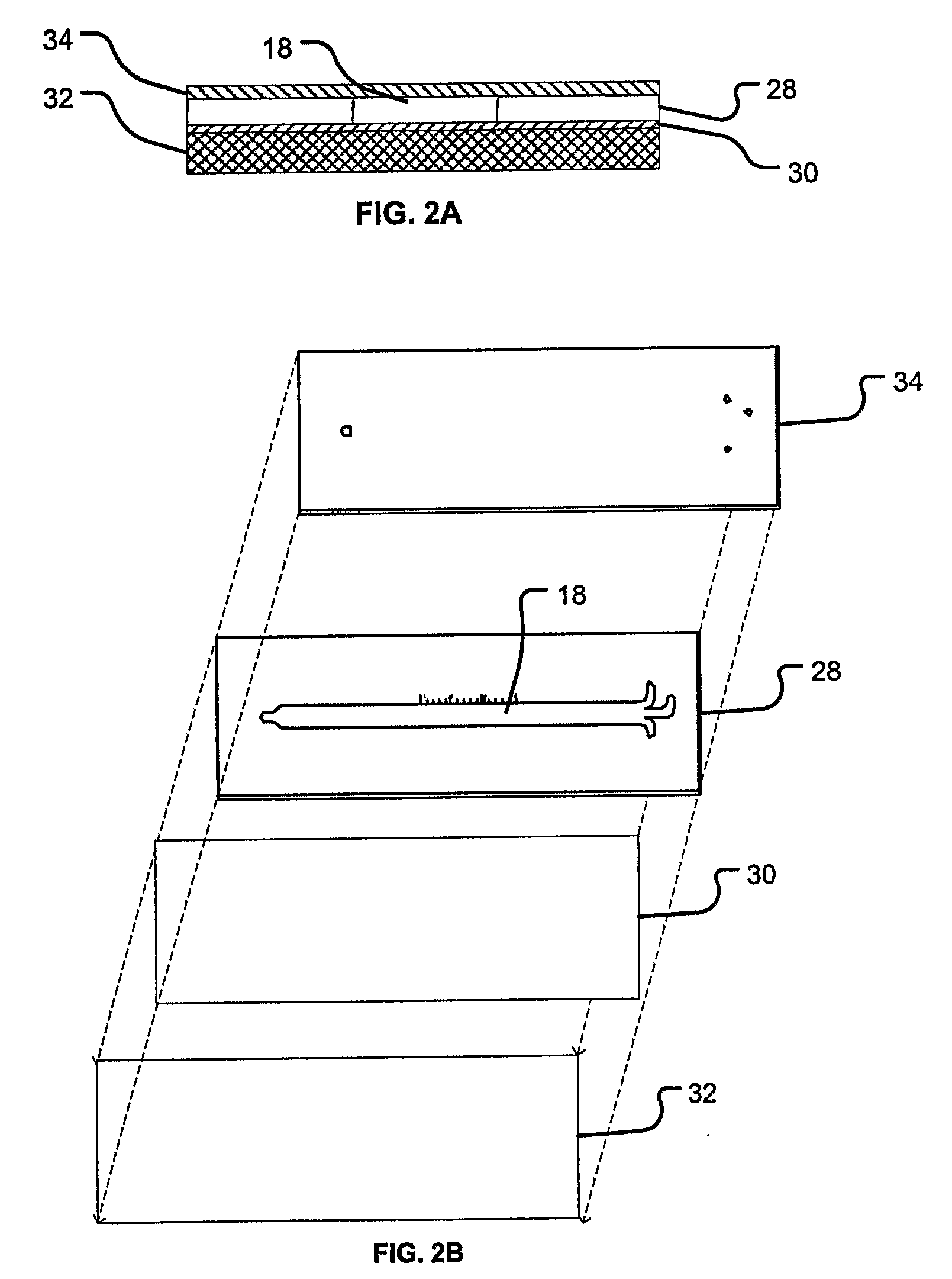
[0009] The microfluidic devices of the present invention are typically in the form of an inexpensive, disposable microfluidic cartridge (a “lab on a chip”) and associated automated imaging and processing equipment. Such devices are exceptionally well suited for running rapid, multiple analyte assays, such as immunoassays. Thus, the devices of the present invention establish a solid basis for reliable point-of-care diagnostics by relatively untrained personnel, although it could be used in larger formats in clinical laboratory settings as well.
[0011] The competitive assay devices of the present invention operate similar to other competitive immunoassay devices, but do not require an enzyme-linked or fluorescently tagged secondary antibody, nor do they require the addition of a labeled competitor species or analog. Instead, the present assay devices use an imaging assembly, such as surface plasmon resonance imaging (SPRI) assembly, that provides for measuring a rate at which antibody molecules bind to specific antigens immobilized on a sensing surface, or vice-versa. The presence of free (i.e., solution phase) competitors reduce the rate of antibody adsorption to the antigens on the sensing surface by binding to their antigen binding sites.

Problems solved by technology

Creating this calibration series adds additional reagent cost and labor to the quantitative ELISA format, but is necessary to control for variations in assay time, reagent activity, and temperature.

Method used


Image

  • Rapid Microfluidic Assay for Quantitative Measurement of Interactions Among One or More Analytes
  • Rapid Microfluidic Assay for Quantitative Measurement of Interactions Among One or More Analytes
  • Rapid Microfluidic Assay for Quantitative Measurement of Interactions Among One or More Analytes

Examples


example i

[0056] As shown in FIG. 8, the immunoassay method of the present invention has been demonstrated experimentally by measuring two analytes in parallel at several regions in a single microfluidic channel. In such experiments, three streams are flowing parallel from the inlets to the outlet. As shown in FIG. 8, flow is from left to right. The first fluid stream comprises a buffer only and is included as a negative control. The second, middle fluid stream comprises a mixture of anti-cortisol and anti-estriol monoclonal antibodies (100 nM each) (shown as “MAbs”). The third fluid stream comprises a buffer with cortisol (50 nM) and estriol (100 nM) (shown as “C & E”). The sensing surface had been patterned with similar surface densities of BSA, BSA-cortisol conjugate (“BSA-C”), and BSA-estriot conjugate (“BSA-E”). The BSA / BSA conjugate triple pattern was repeated five times from left to right. The labels in FIG. 8 are positioned at the second repeated triplet. The gold coating was treated ...

example ii

[0058] One example of a non-limiting protocol of the present invention will now be described. A simplified flow chart illustrating the experimental protocol is provided in FIG. 9. At step 100, the gold coating of the microscope slide is cleaned. However, if the glass slides have been freshly evaporated (within the previous 60 minutes), the cleaning steps of the gold coating can be omitted. The gold coating may be cleaned in a hot base / peroxide wash In such a method, in a clean, flat-bottom glass dish, hydrogen peroxide, ammonium hydroxide, and ddH2O are mixed in a 1:1:5 volumetric ratio (e.g., 10 mL H202, 10 mL NH4OH, 50 mL ddH2O). The solution is heated to 65-75° C. and covered with a watch glass to minimize evaporative loss. The gold coated glass slide is immersed in the heated solution and soaked for approximately 10 minutes. The slide is removed and rinsed first with ddH2O then absolute ethanol. Finally, the slide is blow dried under a dry N2 stream. Other methods of cleaning th...


PUM

PropertyMeasurementUnit
lengthaaaaaaaaaa
heightaaaaaaaaaa
heightaaaaaaaaaa

Abstract

The invention provides microfluidic competitive immunoassay devices and assay methods for rapid, quantitative measurement of binding interactions between analytes and the quantitative determination of an amount (e.g., concentration) of the analyte in an unknown sample.

Description

CROSS-REFERENCE TO RELATED APPLICATIONS [0001] This application claims the benefit of U.S. provisional patent application No. 60 / 622,193, filed Oct. 25, 2004, the entire contents of which are incorporated herein by reference. Throughout this application, various patents and publications are referenced. The disclosures of these patents and publications are incorporated herein by reference to more fully describe the state of the art.STATEMENT AS TO RIGHTS TO INVENTIONS MADE UNDER FEDERALLY SPONSORED RESEARCH AND DEVELOPMENT [0002] Aspects of this research were conducted with funding provided by the National Institute of Dental and Craniofacial Research under Grant No. 5U01 DE014971-03. The U.S. Government may have certain rights in the invention.BACKGROUND OF THE INVENTION [0003] The present invention relates generally to a microfluidic competitive assay device and assay method. More specifically, the present invention uses an imaging assembly, such as surface plasmon resonance imagin...

Claims


Application Information

Patent Timeline
Patent Type & Authority Applications(United States)
IPC IPC(8): C12Q1/70C12M1/34G01N33/487C12Q1/06
CPCG01N33/54366G01N33/54306
Inventor NELSON, KJELL E.
Owner UNIV OF WASHINGTON
Learn More