Method and Apparatus for Well-bore Proximity Measurement While Drilling

a technology of proximity measurement and wellbore, which is applied in the direction of instruments, borehole/well accessories, surveys, etc., can solve the problems of uneconomically low hydrocarbon production under natural conditions, high risk of drilling, and deviation of close to 90

Active Publication Date: 2008-01-24
BAKER HUGHES INC
View PDF26 Cites 80 Cited by
  • Summary
  • Abstract
  • Description
  • Claims
  • Application Information

AI Technical Summary

Benefits of technology

[0011] One embodiment of the disclosure is a method of determining a distance to a first borehole from a second borehole. A time varying magnetic field is produced in the first borehole using a magnet in the second borehole. Magnetization in a magnetic object in the first borehole is produced. A coil in the second borehole is used to produce a signal responsive to a magnetic flux resulting from the magnetization. This signal is used to estimate the distance. The magnetic object in the first borehole may be a casing. The method may further include using the estimated distance to maintain a trajectory of the second borehole in a desired relation to the first borehole. The desired relation may be substantially parallel or intersecting. The method may include conveying a magnet on a bottomhole assembly on a drilling tubular into the second borehole. Producing a time varying field may be done rotating a magnet having a substantially transverse magnetization in the second borehole at a first rotational speed, and...

Problems solved by technology

This procedure is fraught with danger and requires prompt control of hydrocarbons flow in the well.
An error of half a degree can result in a deviation of close to 90 feet at a depth of 10,000 feet.
For various reasons, such as low formation pressure or high viscosity of hydrocarbons in the reservoir, production under natural...

Method used


Image

  • Method and Apparatus for Well-bore Proximity Measurement While Drilling
  • Method and Apparatus for Well-bore Proximity Measurement While Drilling
  • Method and Apparatus for Well-bore Proximity Measurement While Drilling

Examples


Embodiment Construction

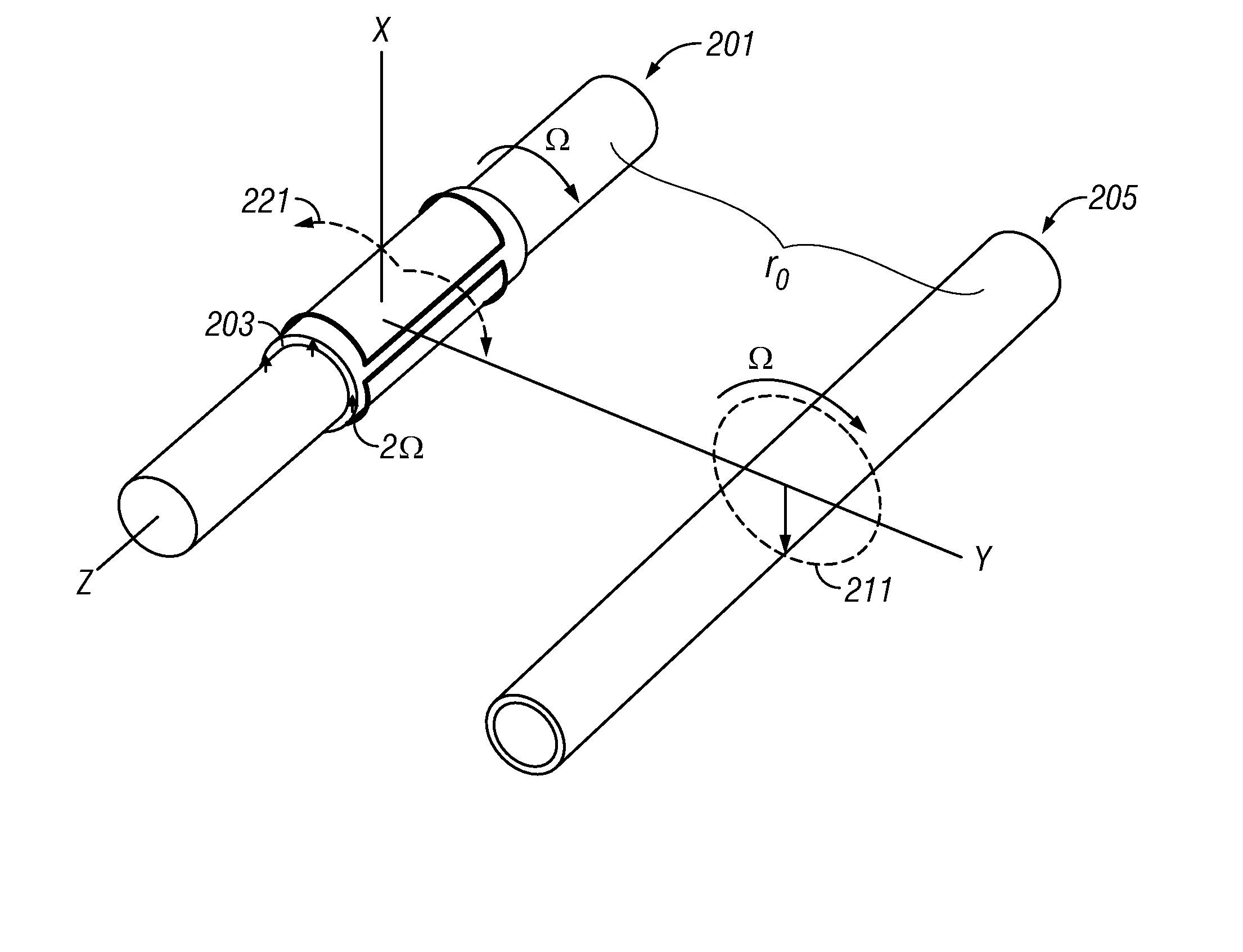
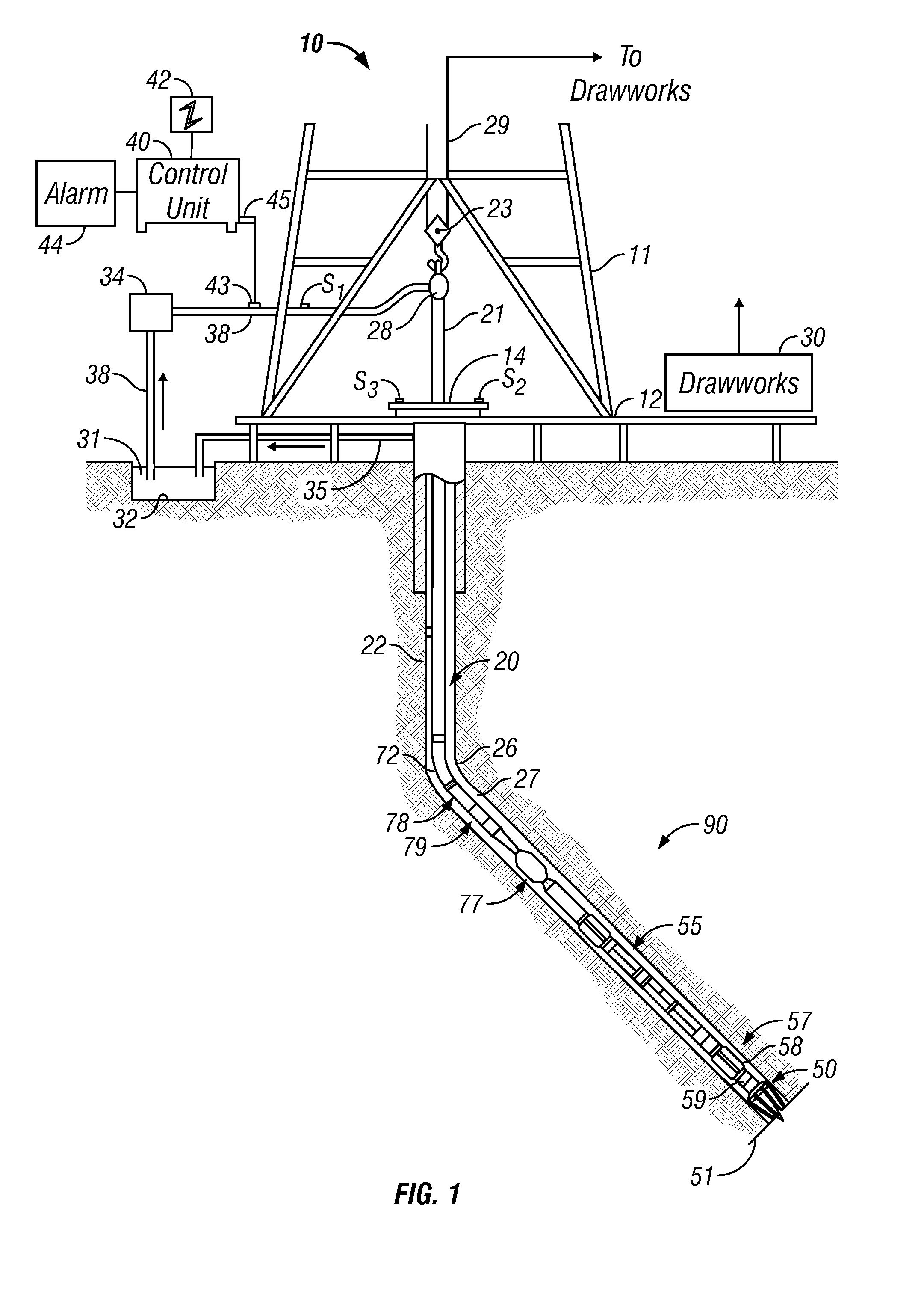
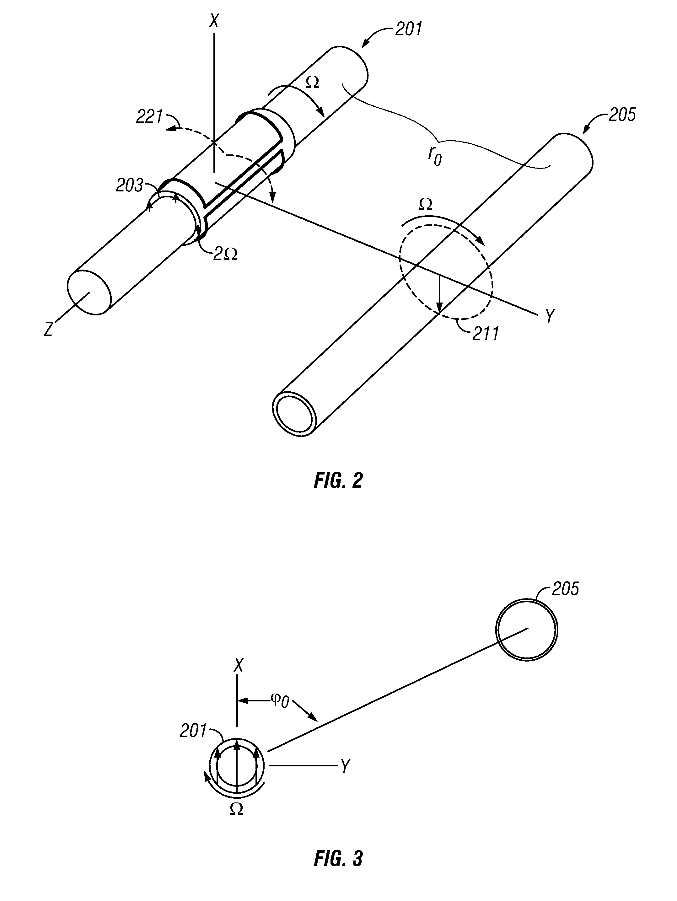
[0023]FIG. 1 shows a schematic diagram of a drilling system 10 with a drillstring 20 carrying a drilling assembly 90 (also referred to as the bottom hole assembly, or “BHA”) conveyed in a “wellbore” or “borehole”26 for drilling the wellbore. The drilling system 10 includes a conventional derrick 11 erected on a floor 12 which supports a rotary table 14 that is rotated by a prime mover such as an electric motor (not shown) at a desired rotational speed. The drillstring 20 includes a tubing such as a drill pipe 22 or a coiled-tubing extending downward from the surface into the borehole 26. The drillstring 20 is pushed into the wellbore 26 when a drill pipe 22 is used as the tubing. For coiled-tubing applications, a tubing injector, such as an injector (not shown), however, is used to move the tubing from a source thereof, such as a reel (not shown), to the wellbore 26. The drill bit 50 attached to the end of the drillstring breaks up the geological formations when it is rotated to dri...


PUM


Abstract

A rotating, transversely magnetized, magnet on a drill collar induces magnetization in a casing of a preexisting well. A coil rotating synchronously with the magnet produces a current at twice the frequency of rotation and having an amplitude that depends upon the distance from the magnet to the preexisting well. Alternatively, a variable magnetic field is produced in the casing using a switchable magnet. It is emphasized that this abstract is provided to comply with the rules requiring an abstract which will allow a searcher or other reader to quickly ascertain the subject matter of the technical disclosure. It is submitted with the understanding that it will not be used to interpret or limit the scope or meaning of the claims.

Description

CROSS-REFERENCE TO RELATED APPLICATION [0001] This application is a continuation-in-part of U.S. patent application Ser. No. 11 / 037,488 filed on Jan. 18, 2005.BACKGROUND OF THE DISCLOSURE [0002] 1. Field of the Disclosure [0003] This disclosure relates generally to methods for performing measurement while drilling applications. More particularly, this disclosure relates to a new and improved apparatus and method for determining a distance to a pre-existing wellbore and controlling drilling operations based on the determination. [0004] 2. Background of the Art [0005] In the process of drilling wells for hydrocarbon production, it is commonly necessary to drill a second well in a predetermined relationship to an existing well. An example of this may be when a blowout occurred in the existing well; two approaches may be taken to control the blowout. One method is to use explosives at the surface and snuff out the fire in the burning well. This procedure is fraught with danger and requi...

Claims


Application Information

Patent Timeline
IPC IPC(8): G01V3/08
CPCE21B47/0905G01N24/081G01V3/32G01R33/381G01R33/3808E21B47/092
Inventor REIDERMAN, ARCADY
Owner BAKER HUGHES INC
Why Eureka
Try Eureka