
Method for manufacturing poorly conductive layers

a technology of poorly conductive layers and manufacturing methods, applied in the direction of vacuum evaporation coating, plasma technique, coatings, etc., can solve the problems of large spattering, inability to operate arc sources in an oxygenous atmosphere, and at best impossible, to achieve a manner suitable for industrial applications, and the coating process to become unstabl

Active Publication Date: 2008-01-24
OERLIKON SURFACE SOLUTIONS AG PFAFFIKON
View PDF17 Cites 42 Cited by
  • Summary
  • Abstract
  • Description
  • Claims
  • Application Information

AI Technical Summary

Benefits of technology

[0010]It is the objective of this invention to introduce a method for depositing marginally conductive and, in particular, nonconductive layers through arc evaporation, avoiding the drawbacks of prior art techniques and making it possible to implement a corresponding arc evaporation process at a high productivity level. Another objective is to provide a method whereby it is possible for the first time, even without using pulsed arc sources and / or simultaneous flushing of the arc sources with an inert gas and the concurrent recoating of the evaporated target surface, to operate over an extended length of time a stable arc evaporation process in a reactive-gas atmosphere, precipitating marginally conductive or nonconductive layers.
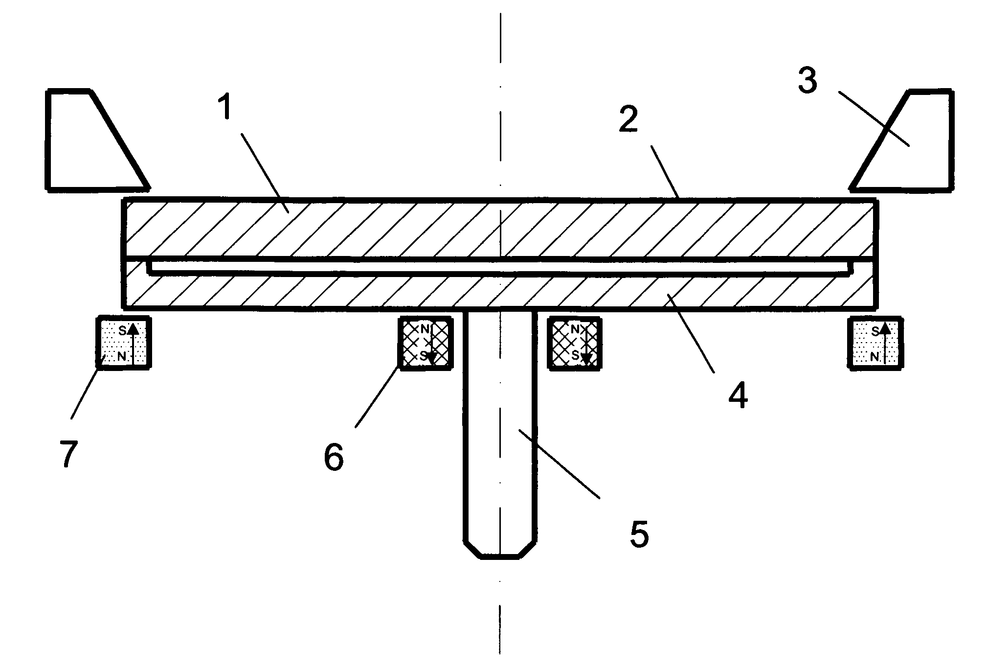
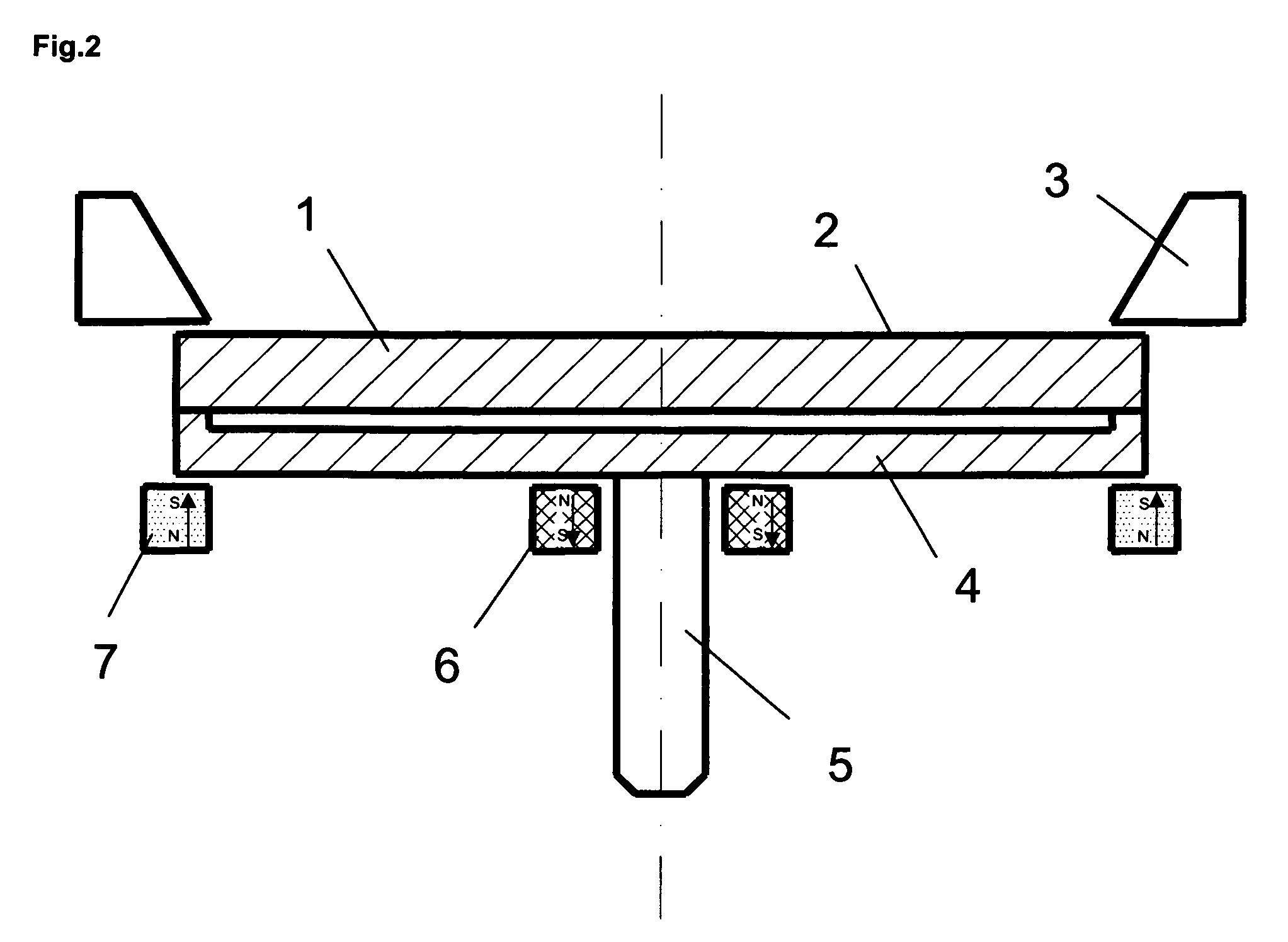
[0011]Surprisingly, it has been found that, with a relatively simple step such as the application of a small outer magnetic field essentially next and perpendicular to the target surface, employing at least one axially polarized coil having a geometry similar to the circumference of the target and with a vertical component Bz as well as an essentially smaller component Br extending radially above or parallel to the larger part of the target surface, it is possible to implement a coating process with long-time stability for producing poorly conductive and, specifically, nonconductive layers. In this case, the vertical component Bz on the target surface is preferably held within a range between 3 and 50 Gauss but more particularly within a range between 5 and 25 Gauss.

Problems solved by technology

Employing prior-art arc techniques, it has been difficult at best, or altogether impossible, to operate arc sources in an oxygenous atmosphere, and especially in pure oxygen, in a manner suitable for industrial applications.
For example, it has been found that using conventional arc sources whose magnetic fields are designed to guide the spark along an essentially circular path results in the deposition of thick oxide layers on the target surfaces, causing the coating process to become unstable.
This leads first to considerable spattering and ultimately to an unstable and eventually extinguished arc.
A process in which arc targets are flushed with an inert gas while the reactive gas is introduced near the substrate surface, cannot always be implemented in view of the substantial technical complexity of the system required, nor is it always successful, given the fact that too high an inert gas concentration results in the precipitation for instance of a mixture consisting of metal and the actually desired metal compound.
On the other hand, it is necessary to provide in addition to the DC power supply a pulsed-current source or a special, correspondingly expensive single generator capable of overlaying a suitable pulsed-current pattern on the basic operating current.
There is no known prior-art method whereby magnetic fields are optimized in terms of arc evaporation for producing insulating or oxidic layers in the process of which nonconductive or at least poorly conductive layer sections are produced, at least temporarily, on the target surface as well.
To date, because of the difficulties referred to above, no such arc methods have been employed in industrial applications for depositing this type of layers, nor have they been mentioned in prior art on more than a few isolated occasions.
That method, however, presents a problem for several reasons.
For another, the mutual coating will always be at the expense of the deposition rate on the work pieces and, consequently, of the economic effectiveness of the method.

Method used


Image

  • Method for manufacturing poorly conductive layers
  • Method for manufacturing poorly conductive layers
  • Method for manufacturing poorly conductive layers

Examples


Embodiment Construction

[0010]It is the objective of this invention to introduce a method for depositing marginally conductive and, in particular, nonconductive layers through arc evaporation, avoiding the drawbacks of prior art techniques and making it possible to implement a corresponding arc evaporation process at a high productivity level. Another objective is to provide a method whereby it is possible for the first time, even without using pulsed arc sources and / or simultaneous flushing of the arc sources with an inert gas and the concurrent recoating of the evaporated target surface, to operate over an extended length of time a stable arc evaporation process in a reactive-gas atmosphere, precipitating marginally conductive or nonconductive layers.

[0011]Surprisingly, it has been found that, with a relatively simple step such as the application of a small outer magnetic field essentially next and perpendicular to the target surface, employing at least one axially polarized coil having a geometry simila...


PUM

PropertyMeasurementUnit
Fractionaaaaaaaaaa
Fractionaaaaaaaaaa
Fractionaaaaaaaaaa

Abstract

Method for producing poorly conductive and in particular nonconductive layers on at least one work piece by means of a vacuum-coating process in which an electric arc discharge is activated between at least one anode and the cathode of an arc source in a reactive-gas atmosphere, whereby on the surface of a target that is electrically connected to the cathode either none or only a small outer magnetic field is generated that extends essentially perpendicular to the target surface for assisting the evaporation process, the degree of recoating of the target surface by other coating sources is less than 10%, and the magnetic field is generated with a magnet system that encompasses at least one axially polarized coil with a geometry similar to the circumference of the target.

Description

THE TECHNOLOGY[0001]Method for producing insulating layers by means of one or several arc sources, with only a minor magnetic field, or none, generated on the target surface for assisting in the evaporation process. More specifically, the method serves to produce oxides and to operate the said minimum of one arc source in an oxygenous atmosphere.PRIOR ART[0002]Employing prior-art arc techniques, it has been difficult at best, or altogether impossible, to operate arc sources in an oxygenous atmosphere, and especially in pure oxygen, in a manner suitable for industrial applications. For example, it has been found that using conventional arc sources whose magnetic fields are designed to guide the spark along an essentially circular path results in the deposition of thick oxide layers on the target surfaces, causing the coating process to become unstable. The target surface on which the spark travels becomes constricted, i.e. the spark travels on an ever diminishing surface of the targe...

Claims


Application Information

Patent Timeline
IPC IPC(8): H05H1/32C23C16/00
CPCC23C14/325H01J37/34H01J37/3266H01J37/32055
Inventor RAMM, JURGENWIDRIG, BENOWOHLRAB, CHRISTIAN
Owner OERLIKON SURFACE SOLUTIONS AG PFAFFIKON
Learn More