Microscale capacitive deionization apparatus

a capacitive deionization and micro-scale technology, applied in the direction of fluid pressure measurement, liquid/fluent solid measurement, peptide measurement, etc., can solve the problems of low power consumption and very little energy required to achieve the effect of reducing the chance of electrical shock

Active Publication Date: 2008-01-31
VECENERGY AEGIR
View PDF23 Cites 45 Cited by
  • Summary
  • Abstract
  • Description
  • Claims
  • Application Information

AI Technical Summary

Benefits of technology

[0018] Waste disposal from the present invention, when necessary, can be dealt with the same manner as with other desalination techniques. Possible solutions include evaporation of the brine, dumping of waste fluid or deep well injection techniques. The safety aspects of this device are limited only to the types of contaminated water or fluid that are passed through the device. With proper design of the circuits and power supplies there should be little chance of electrical shocks when the device is used correctly.
[0019] Accordingly, it is an objective of the instant invention to provide a device to remove ions from a fluid utilizing electromagnetic forces created by charged plates electrically insulated from the fluid.
[0020] It is a further objective of the instant invention to provide a device to remove ions from a fluid utilizing a continuous flow system.
[0021] It is yet another objective of the instant invention to provide a device to remove ions from a fluid which does not require regeneration or cleaning of the charged plates.
[0022] It is a still further objective of the invention to provide a device to remove ions from a fluid which does not require a phase change of the fluid, e.g. distillation.
[0023] It is a still further objective of the invention to provide a device to remove ions from a fluid which does not require a semi-permeable barrier like reverse osmosis.

Problems solved by technology

This technique requires very little energy due to the use of low currents and high voltages.
This technology can be a very low energy system, requiring at a minimum a step-up transformer to increase the voltage while simultaneously decreasing the current, which results in a very low power consumption.

Method used


Image

  • Microscale capacitive deionization apparatus
  • Microscale capacitive deionization apparatus
  • Microscale capacitive deionization apparatus

Examples


Embodiment Construction

[0059] While the present invention is susceptible of embodiment in various forms, there is shown in the drawings and will hereinafter be described a presently preferred, albeit non limiting, embodiment with the understanding that the present disclosure is to be considered an exemplification of the present invention and is not intended to limit the invention to the specific embodiments illustrated. Also, it is understood that the present invention is capable of removing ions from various fluids, in addition to water.

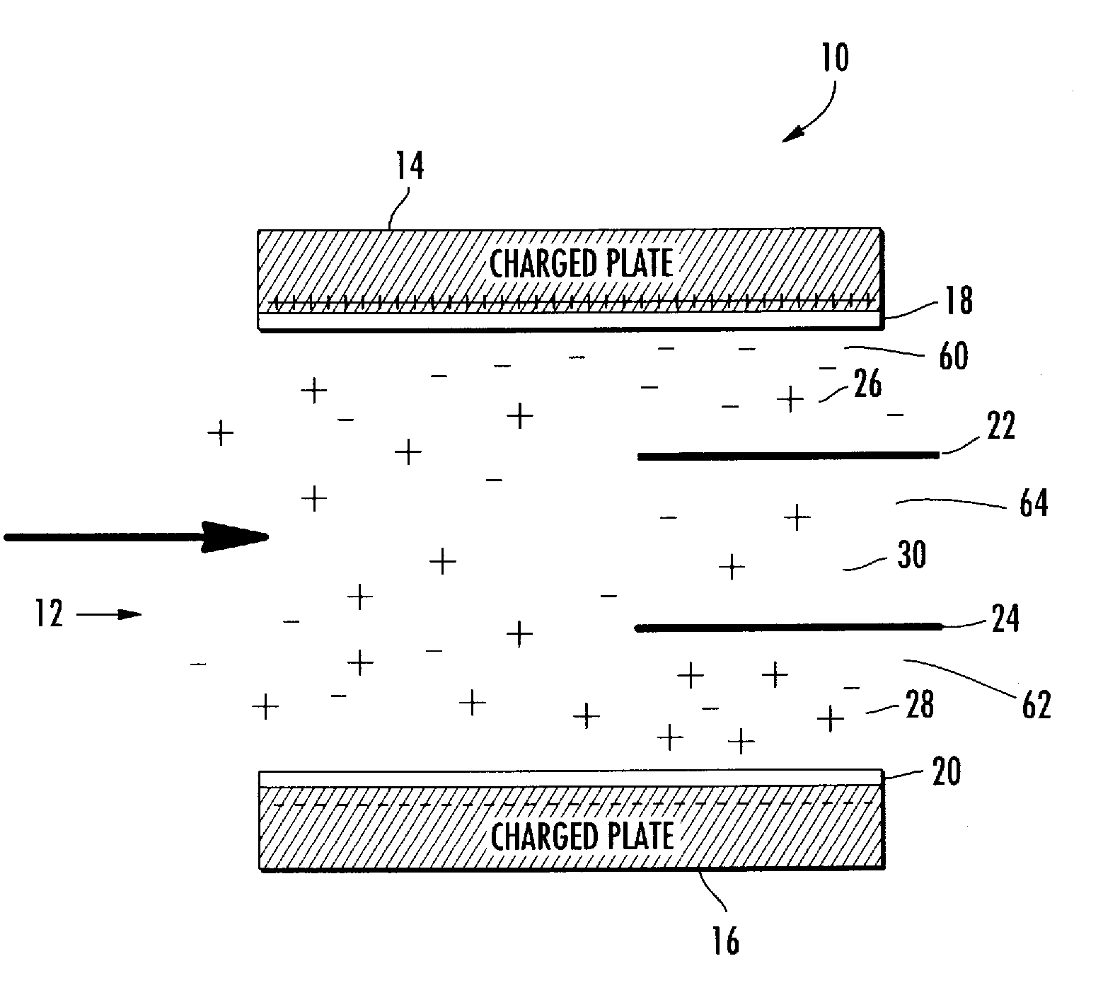
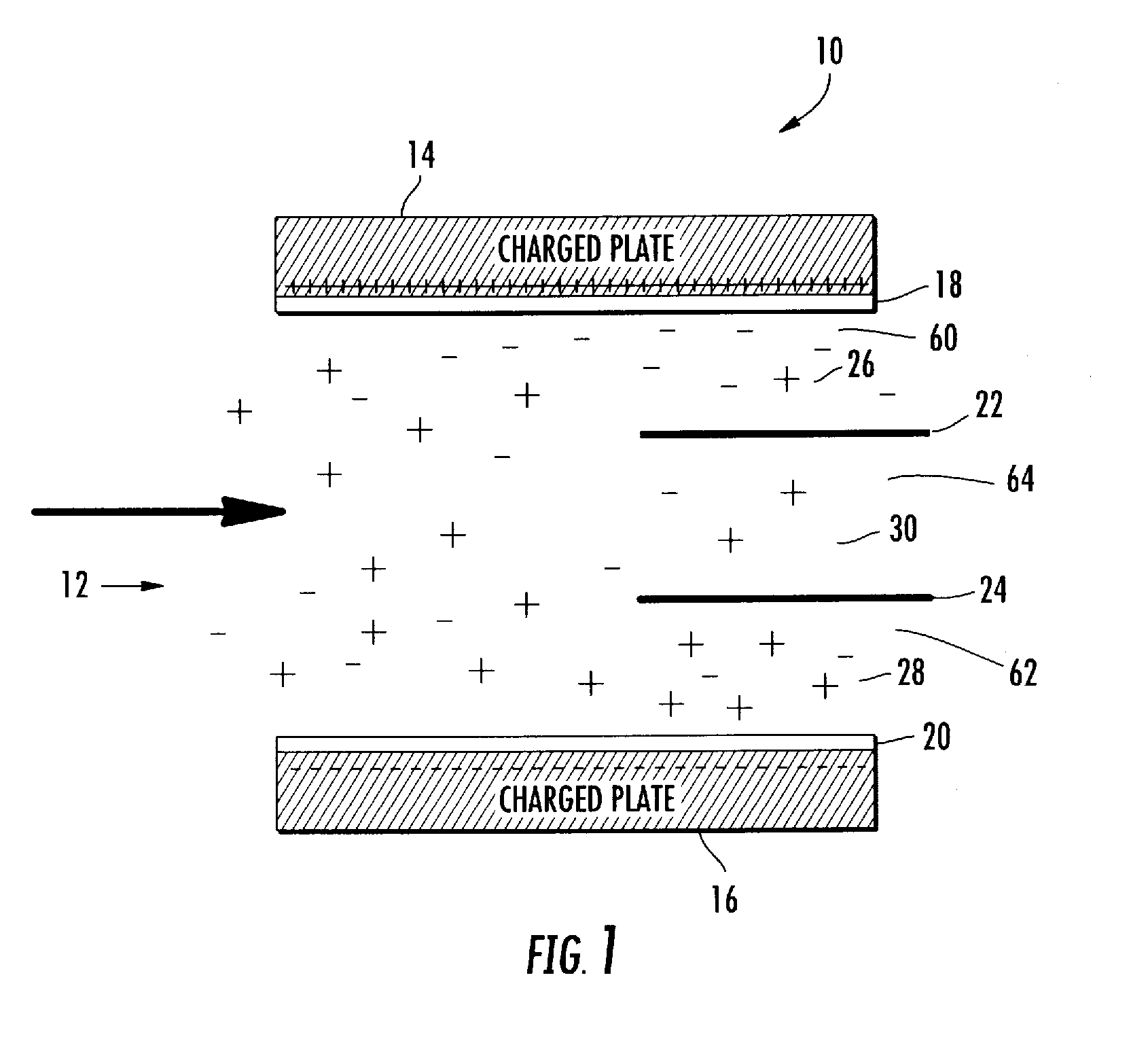
[0060] The basis operation of the present invention is illustrated in FIG. 1. The fluid or ionic fluid to be deionized is fed in the device 10 and flows down the main channel 12. The fluid stream passes between charged electrodes 14 and 16. The positive charged electrode 14 has a positive charge and attracts negative ions toward the upper portion of the fluid stream. The negative charge electrode 16 has a negative charge and attracts positive ions toward the lower portio...


PUM

PropertyMeasurementUnit
distanceaaaaaaaaaa
voltagesaaaaaaaaaa
voltagesaaaaaaaaaa

Abstract

The present device is a microchannel separator that uses a separation driving force created by an electric field. An ionic fluid flows through the microchannels and is subjected to an electric field by two spaced apart parallel electrodes possessing an electric charge. The ions in the ionic fluid are attracted towards the charged electrodes and thus are concentrated in the region of flow near the charged electrodes and depleted from the central region of flow between the charged electrodes. The charged electrodes are insulated from the ionic fluid by an impermeable barrier which prevents arcing and adherence of the ions to the charged electrodes. After a sufficient length of passage of the ionic fluid through a main channel two blocking plates separate the flow into a central and two outer output channels. The central channel draws a portion of the ionic fluid from the central region of the main channel that has fewer ions than the ionic fluid in the regions near the charged electrodes. The concentrated ionic fluid in the outer channels is discharged separately from the central channel.

Description

CROSS REFERENCE TO RELATED APPLICATIONS [0001] This application claims the benefit of U.S. Application No. 60 / 807,581, entitled Micro Capacitive Deionization Apparatus, filed on Jul. 17, 2006, the entire disclosure of which is hereby incorporated by reference.FIELD OF THE INVENTION [0002] The present invention relates to capacitive deionization of fluids and more particularly to flow through capacitors for removing ionic substances from an ionic fluid. BACKGROUND OF THE INVENTION [0003] Water contaminated with salts over 1,000 parts per million (ppm) is not fit for human consumption. In many parts of the World, the major sources of water are brackish and must be processed before they are fit for human consumption. Not only are these salty waters found in coastal areas where the major water source is seawater, but also in landlocked areas where the only available water lies deep under the surface of the Earth. Much deep-well water is full of dissolved solids, including a number of sa...

Claims


Application Information

Patent Timeline
Patent Type & Authority Applications(United States)
IPC IPC(8): C02F1/48
CPCC02F1/4691
Inventor JOHNSON, BRENDAN
Owner VECENERGY AEGIR
Why Eureka
Try Eureka