[0002] The number of new hospital-based facilities for charged particles therapy is growing quickly, especially in Japan and in the USA.
Proton therapy is becoming a realistic therapeutic possibility for treating well-selected
cancer types in centralized large hospitals.
[0004] This approach to
proton therapy is attracting more and more the interest from industry and hospitals internationally, because this method is now being recognized as the preferred method for providing intensity-modulated
radiation therapy (IMRT) using proton beams, a technique now known in the
community as intensity-modulated-proton therapy (IMPT). This technique (based on the modulation of the totally delivered beam
fluence) should not be confused with the active
dynamic control of the beam intensity (the instantaneous
dose rate) described later below. In contrast to
photon-IMRT, with proton
beam scanning one can control independently the flux, the range, the position and direction of each proton pencil beam, making use of all available
degrees of freedom including the
depth of penetration of the proton beam into the patient. With this method similar results can be obtained as with IMRT but with improved conformity and with a significant reduction (by a factor of two or three) of the
dose burden on the healthy tissues surrounding the tumor.
[0009] a) the possibility to apply conformal therapy with variable modulation of the range delivered “all by computer” without the need to use field specific
beam shaping devices like collimators and compensators;
[0034] The use of a reduced range of magnetic scanning—on a small compact
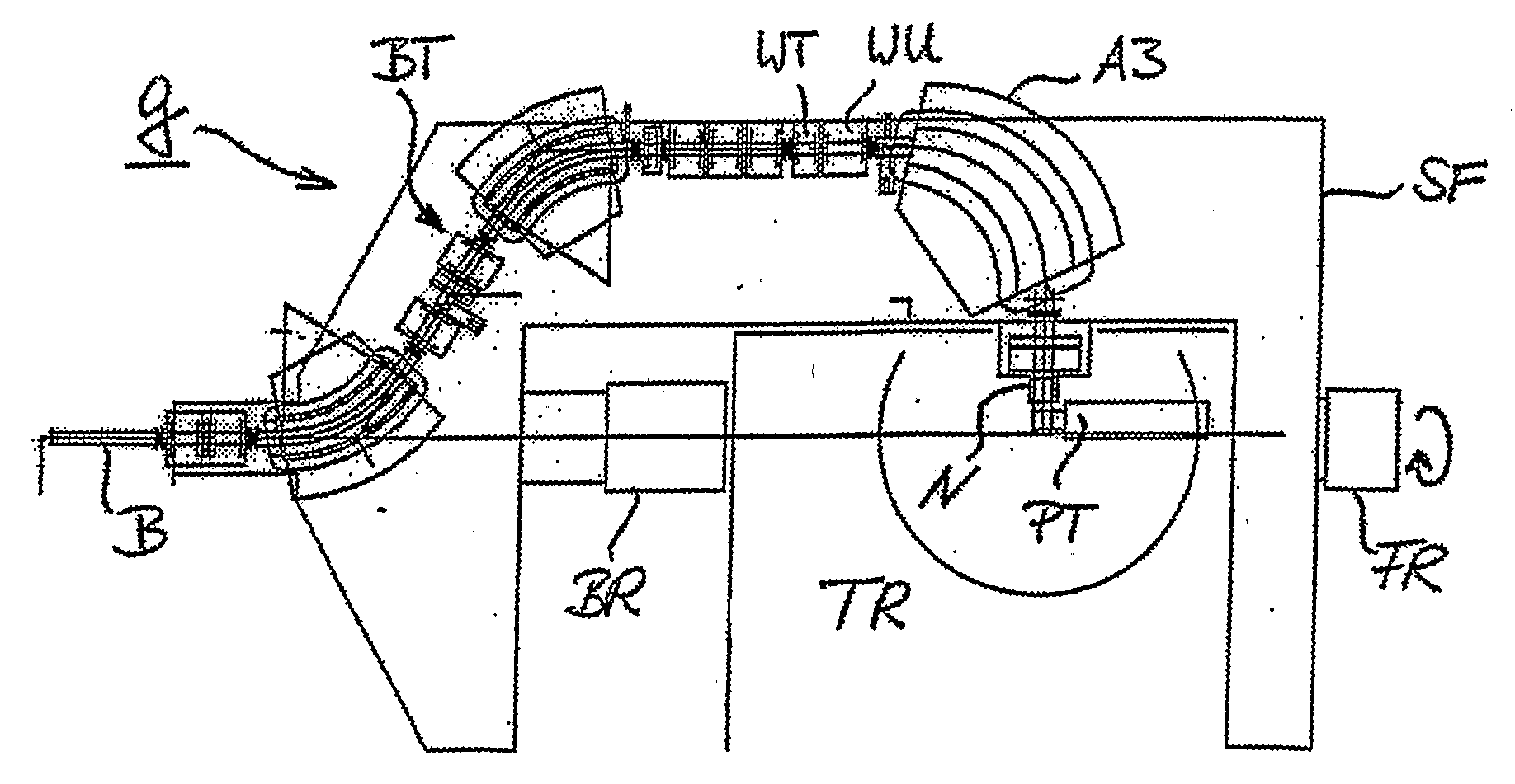
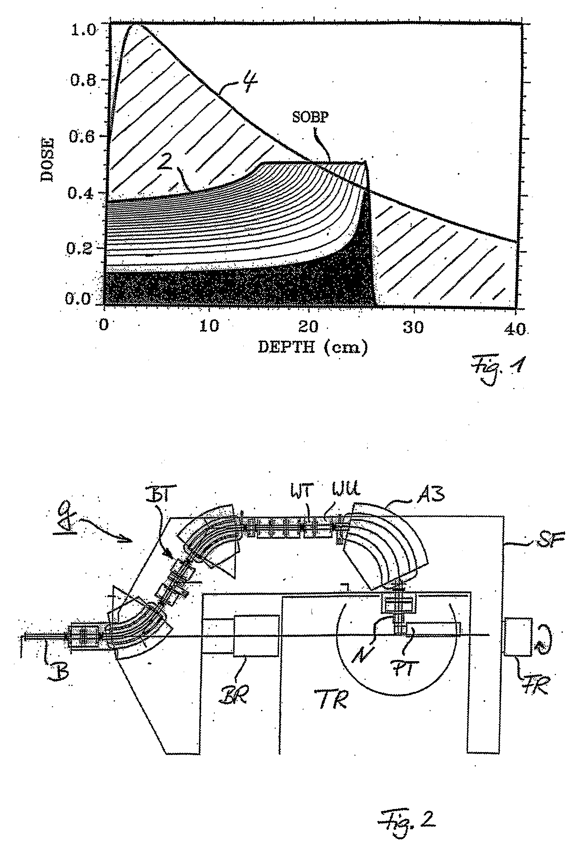
nozzle and a small air gap to the patient allow to design a very compact gantry which brings an almost unscattered (due to the
short distance) proton beam into the target volume. The use of the two-dimensional parallelism of scanning—for the
field size extension using the patient table on the basis of a “geometrical” field patching—which opens up the option to use a slow continuous table motion during
multiple target rescannings in order to compensate the comparably small cross-sectional scanning area at the
nozzle.
[0035] The possibility, by virtue of the design of the
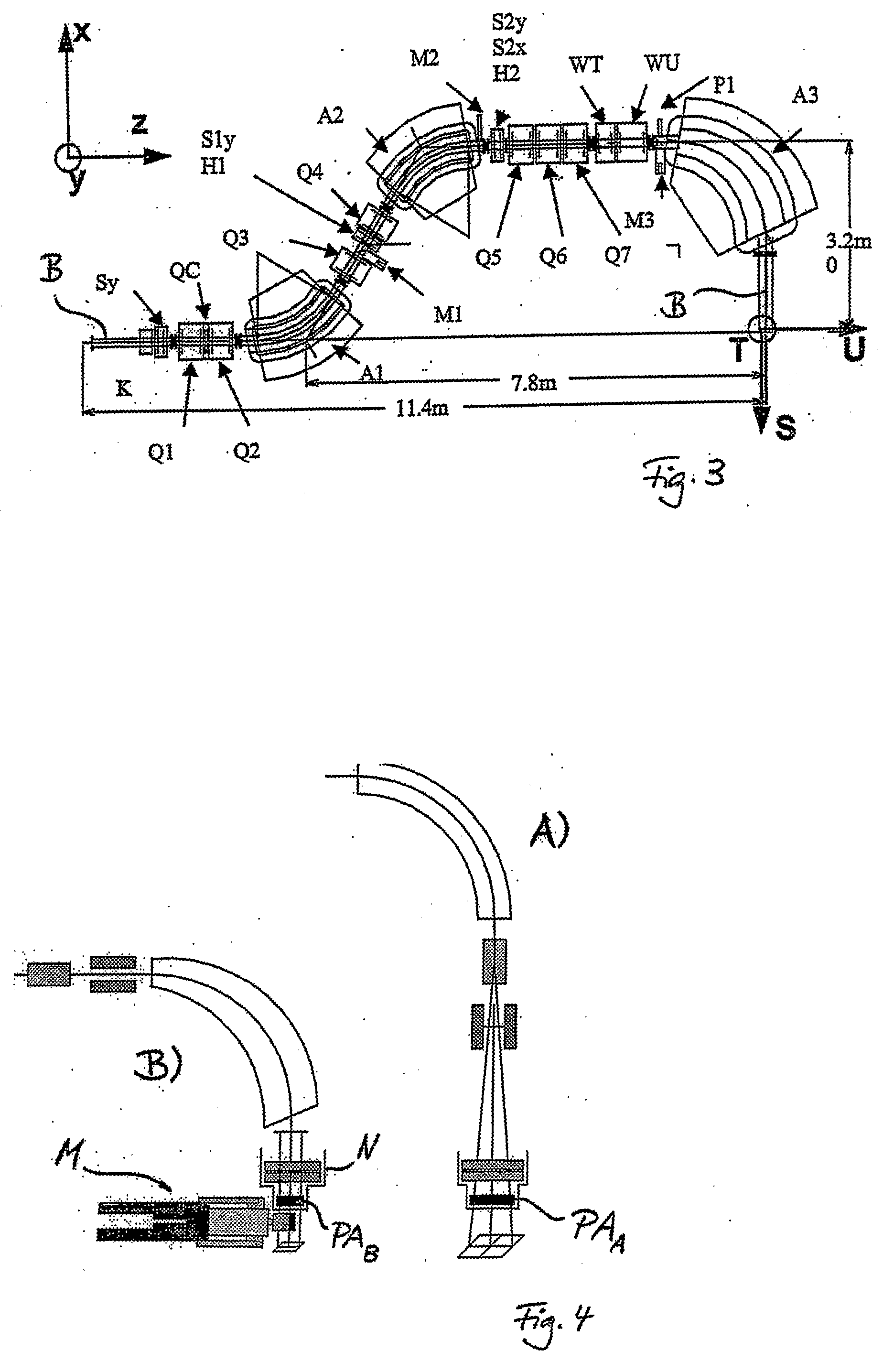
beam optics, to scan the beam in two dimensions while keeping the direction and the shape of the beam unchanged (
parallel beam scanning) is a major characteristics of the PSI Gantry 2. Strong emphasis is given on the utilization of this important feature. The parallelism of scanning can be used for extending the range of
beam scanning beyond the given magnetic scanning range, by combining it with the patient table motion in a simple procedure, which is independent of treatment planning (“geometrical” field patching). While using a geometrical field patching technique the patient table can be moved very slowly and continuously, by compensating the displacement of the table motion with an offset applied to the sweepers (field patching applied with continuous table motion). This approach is very attractive especially in the context of
multiple target repaintings, which are needed in the presence of
organ motion (slow table motion during
multiple target repaintings). The geometric field patching method allows overcoming the problems posed by a limited range of magnetic scanning. This feature can then be used for designing a
nozzle which is small in size in both transverse directions to the beam (slim very compact nozzle) as given by the defined size of the cross-sectional scanning area. The use of a slim nozzle is the preferred solution for placing the patient very close to a pre-absorber system and to the beam monitors, both enclosed in the nozzle (small air gap to the patient), without colliding with patient shoulders, to avoid the broadening of the beam due MCS in the air gap to the patient.
[0040] Therefore, it is now possible to perform the magnetic scan (at each iso-energy layer) along the target contour (at that proton depth) and on similar
equidistant contours in the interior of the target (contoured double magnetic scanning). The concentric contours are scanned with close-to-maximum speed by shaping the
dose using the beam
intensity modulation controlled at the
ion source of the accelerator. By this method scanning speed is gained and thus a large amount of target repaintings can be applied. Additionally, the best possible quality of the lateral fall-off of the
dose distribution at the edge of the field can be obtained and the dynamics for the beam intensity variations can be kept low, while working with maximum speed of scanning. By virtue of the 1:1 imaging of the
beam optics of Gantry 2 from the
coupling point of the gantry to the
isocenter, an imaged (virtual) collimation on the scanned beam spots can be applied by using a (real)
collimator block (moving radially and azimuthally) at the
coupling point of the gantry (contoured double magnetic scanning with imaged collimation applied to a scanned broad beams).


