Electronic Device and Time Adjustment Method

a technology which is applied in the field of electronic devices and time adjustment methods, can solve the problems of increasing power consumption of electronic devices, taking a long time to adjust the time kept by the timepiece, and difficult for the receiver to receive signals from the gps satellite, etc., and achieves the effect of high precision and low power consumption

Inactive Publication Date: 2008-02-07
SEIKO EPSON CORP
View PDF18 Cites 46 Cited by
  • Summary
  • Abstract
  • Description
  • Claims
  • Application Information

AI Technical Summary

Benefits of technology

[0013]The present invention provides an electronic device that enables adjusting the time with high pre

Problems solved by technology

Depending on the location of the user, tall buildings and other structures can interfere with signal reception from the orbiting GPS satellites, and it may therefore take a long time to adjust the time kept by the timepiece.
When the user is indoors in a building, it can be particularly difficult for the receiver to receive signals from the GPS satellites.
This obviously increases power consumption by the

Method used


Image

  • Electronic Device and Time Adjustment Method
  • Electronic Device and Time Adjustment Method
  • Electronic Device and Time Adjustment Method

Examples


embodiment 1

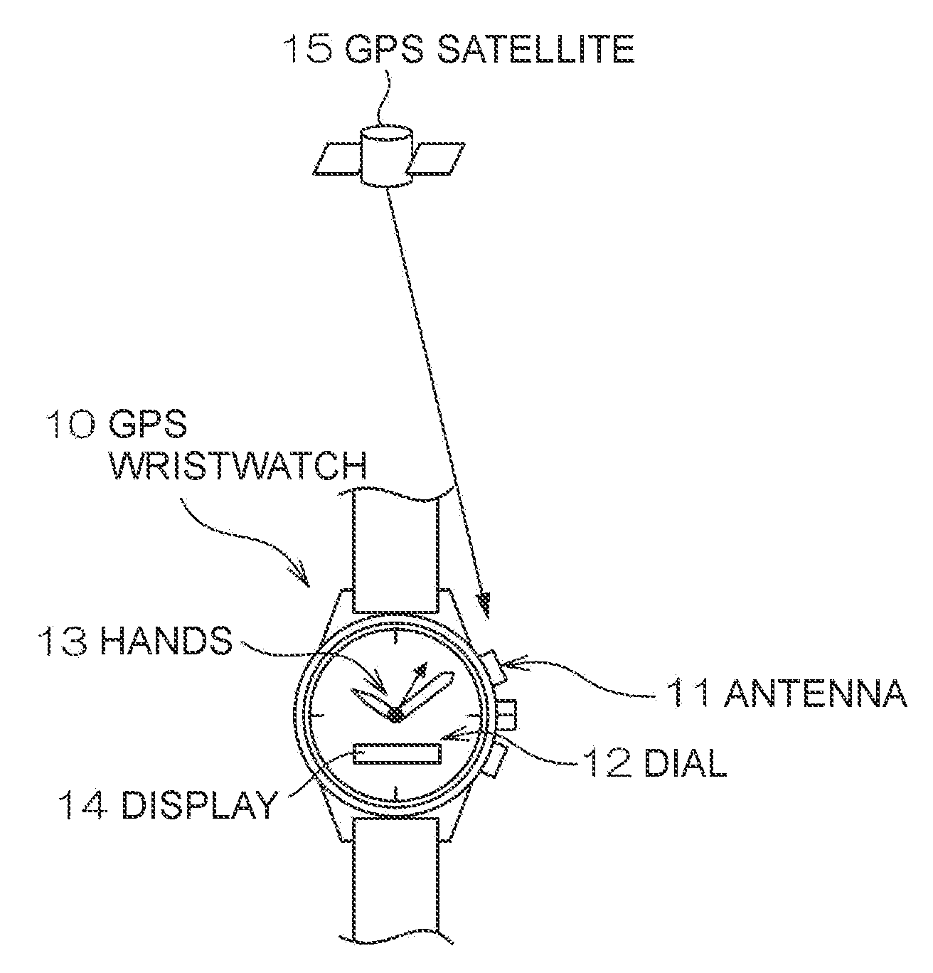
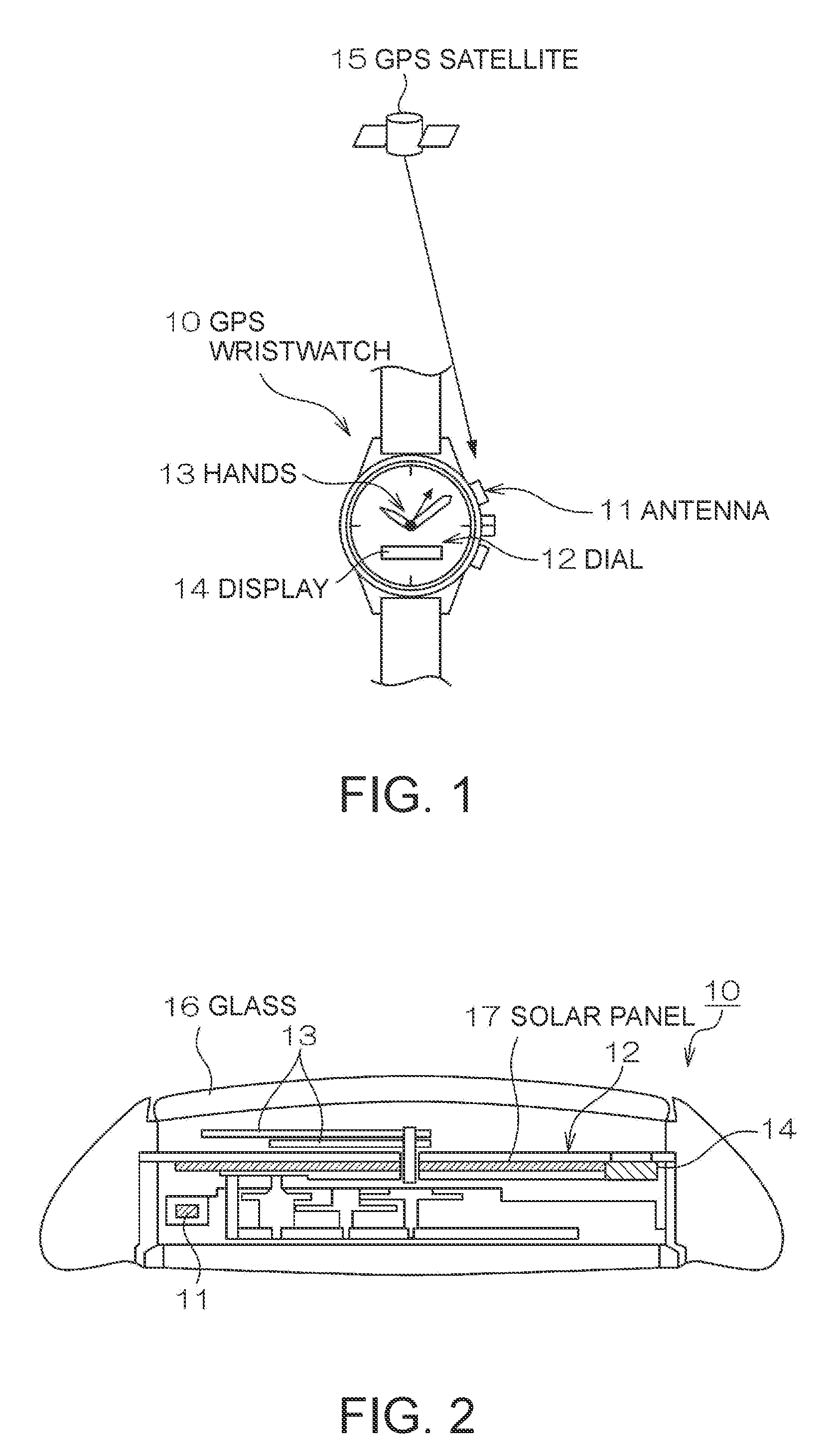
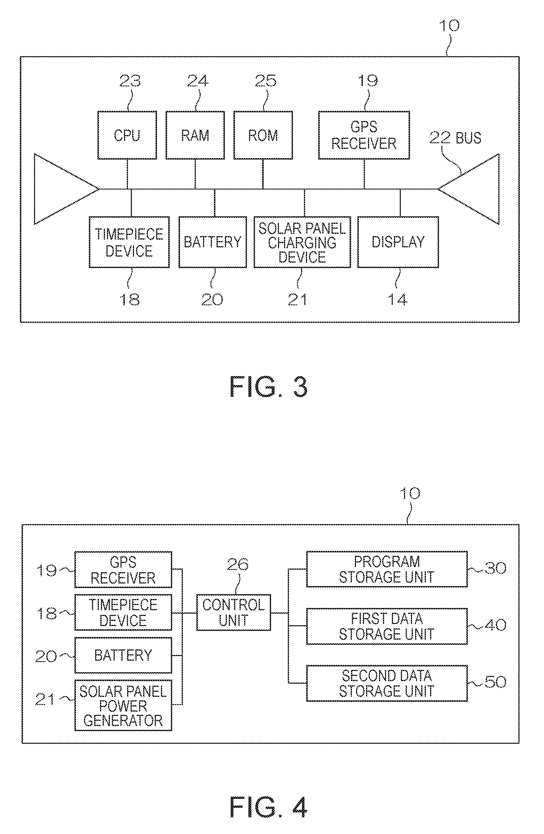
[0109]FIG. 1 is a schematic diagram of a wristwatch with a GPS time correction device 10 (a “GPS wristwatch” below) as a first embodiment of an electronic device according to the present invention. FIG. 2 is a side section view of the GPS wristwatch 10 shown in FIG. 1, and FIG. 3 is a block diagram showing the main hardware configuration of the GPS wristwatch 10 shown in FIG. 1.

[0110]As shown in FIG. 1 and FIG. 2 this GPS wristwatch 10 has a dial 12, hands 13 including a long hand and a short hand, and a display 14 composed of the dial and an LED panel for displaying messages rendered on the front. The display 14 is not limited to an LED device and could be an LCD device or an analog display, for example.

[0111]As shown in FIG. 2, a glass 16 covers the surface of the dial 12.

[0112]As also shown in FIG. 1 and FIG. 2 the GPS wristwatch 10 has an antenna 11, and the antenna 11 is used to receive signals from the GPS satellites 15 travelling on prescribed orbits above the Earth in space....

second embodiment

[0222]FIG. 14 is a schematic diagram of a wristwatch with a GPS time correction device 100 (a “GPS wristwatch” below) as an example of a second embodiment of an electronic device according to the present invention. FIG. 15 is a side section view of the GPS wristwatch 100 shown in FIG. 14.

[0223]As shown in FIG. 14 and FIG. 15 this GPS wristwatch 100 has a dial 12, a time display unit 28 including a second hand 13b, a minute hand 13a, and an hour hand 13c, a display 14 composed of an LCD panel 130 on which messages are displayed, and a date display unit 122 on which the date is displayed. The GPS wristwatch 100 also has an operating unit 27 which the user operates in response to messages presented on the display 14.

[0224]Note that like parts in this second embodiment and the first embodiment are identified by the same reference numerals, duplicative description is omitted, and primarily the differences between the embodiments are described below.

[0225]The internal arrangement of the G...


PUM


Abstract

An electronic device having a reception unit that receives satellite signals from positioning information satellites orbiting the Earth; a time information generating unit that generates time information; a time correction information storage unit that stores time correction information for correcting the time information; a time correction information generating unit that generates the time correction information based on the satellite signals; an environmental information acquisition unit that gets information about the reception unit environment; a reception environment information generating unit that generates reception environment information for the reception unit based on the environment information; and a positioning information satellite selection unit that selects the positioning information satellite from which signals are to be received by the reception unit based on the reception environment information.

Description

CROSS-REFERENCE TO RELATED APPLICATIONS[0001]Japanese Patent application No. (s) 2006-213480 and 2006-213481 are hereby incorporated by reference in their entirety.BACKGROUND[0002]1. Field of Invention[0003]The present invention relates to an electronic device that sets the time based on signals received from a GPS satellite, for example, and to a time correction method for the electronic device.[0004]2. Description of the Related Art[0005]The Global Positioning System (GPS), which is a system enabling a receiving device to determine its own position, uses satellites (GPS satellites) that each orbit the Earth on a specific path. Each GPS satellite has an on-board atomic clock and keeps time with extremely high precision.[0006]Japanese Unexamined Patent Appl. Pub. 08-15463 (see the abstract), for example, teaches a method of using data from the atomic clock of a GPS satellite to correct the time kept by a timepiece with high precision.[0007]However, in order to get atomic clock data ...

Claims


Application Information

Patent Timeline
IPC IPC(8): G01S1/00G01K7/00H01L31/042G01P15/00G01S19/14G01S19/23G01S19/34G01S19/35
CPCG01S19/14G01S19/23G01S19/34G04R20/02G04G5/002G04G21/04G01S19/35
Inventor HONDA, KATSUYUKIURANO, OSAMUFUJISAWA, TERUHIKOMATSUZAKI, JUN
Owner SEIKO EPSON CORP
Why Eureka
Try Eureka