Method and apparatus for temperature control in a continuous casting furnace

a continuous casting furnace and temperature control technology, applied in the field of continuous casting furnaces, can solve the problems of reducing the cooling rate of cast ingots, residual stress and cracking tendency in cast ingots, and the inability to use water spray and forced air cooling in pam and ebm to control the temperature of cast ingots

Active Publication Date: 2008-02-14
HOWMET AEROSPACE INC
View PDF5 Cites 36 Cited by
  • Summary
  • Abstract
  • Description
  • Claims
  • Application Information

AI Technical Summary

Benefits of technology

[0008]The present invention provides an apparatus comprising a continuous casting mold adapted to produce a metal cast; a metal cast pathway which is disposed below the mold and adapted to allow the metal cast to move therethrough; and a temperature control mechanism including a portion which is disposed adjacent the pathway

Problems solved by technology

However, for the casting of segregation-prone and cracking-prone alloys such as tool steels, an insulation blanket is sometimes used to cover the surface of the cast ingot and slow down the ingot cooling rate.
This results i

Method used


Image

  • Method and apparatus for temperature control in a continuous casting furnace
  • Method and apparatus for temperature control in a continuous casting furnace
  • Method and apparatus for temperature control in a continuous casting furnace

Examples


Embodiment Construction

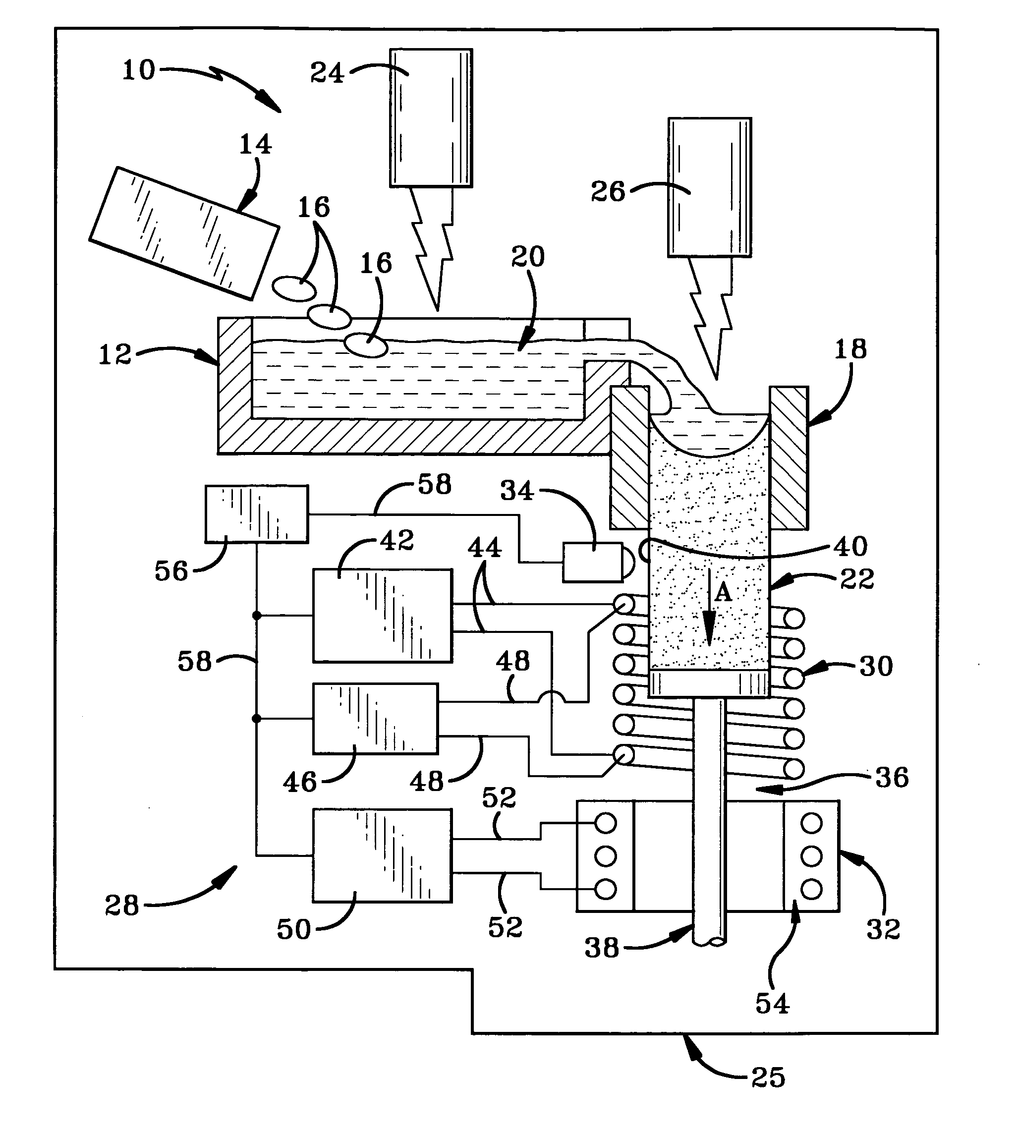
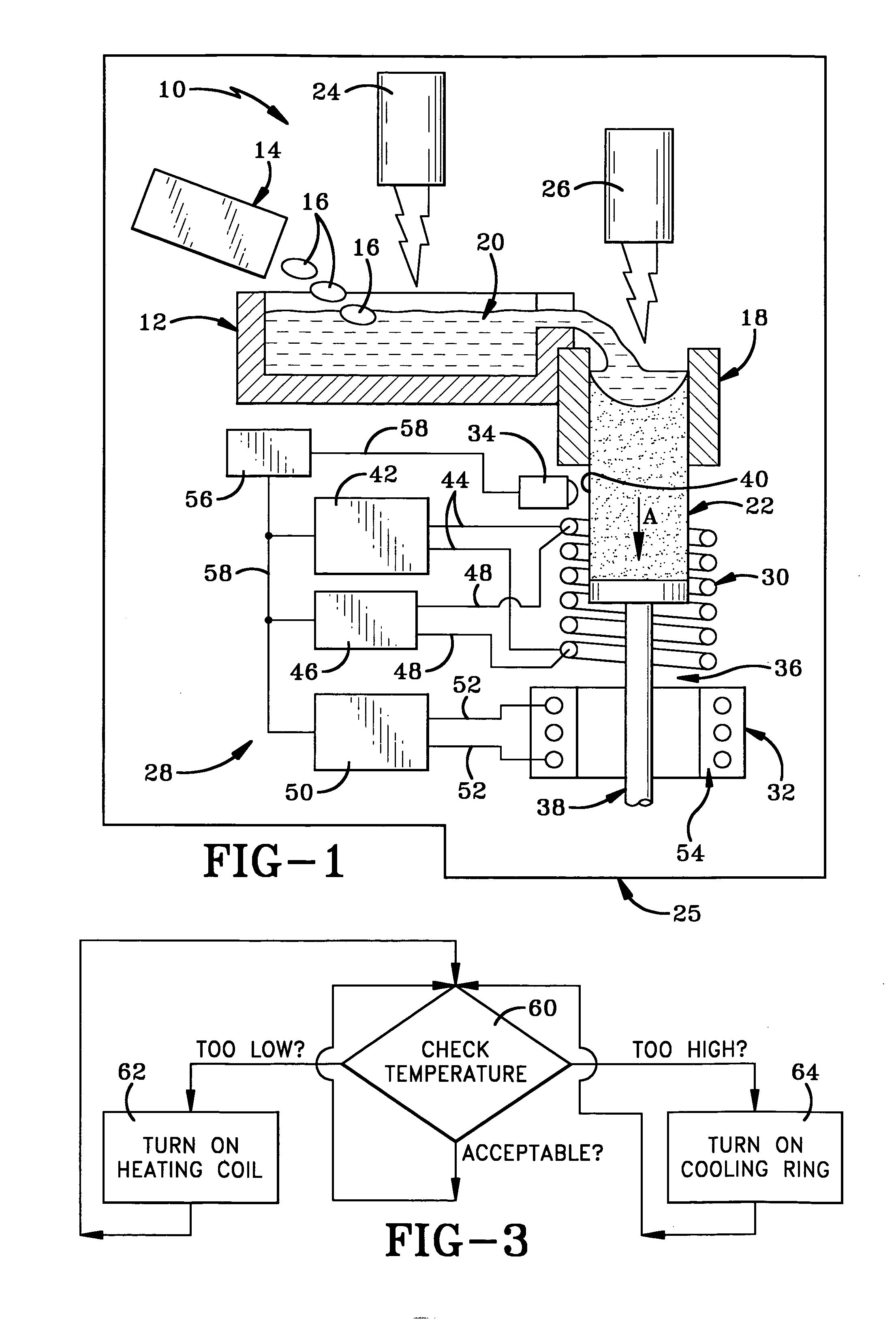
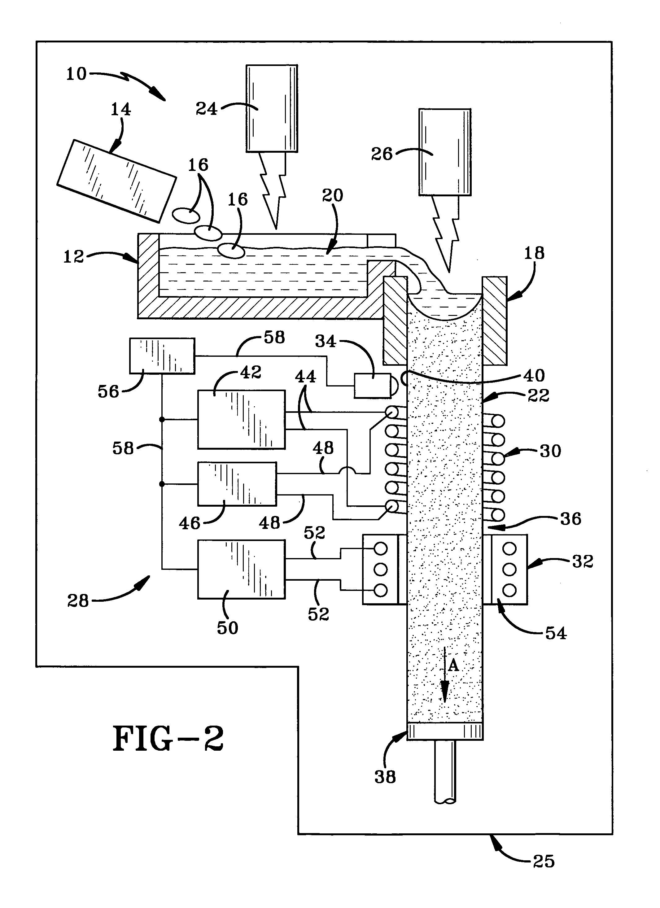
[0014]The continuous casting furnace of the present invention is indicated generally at 10 and FIGS. 1 and 2. Furnace 10 includes a melting hearth 12 having a melting cavity and a feed mechanism 14 for feeding solid metal feed material 16 into the melting cavity of hearth 12. Furnace 10 further includes a continuous casting mold 18 situated for receiving molten material 20 from an overflow of melting hearth 12 in order to form a metal cast 22 therewith. First and second heat sources 24 and 26 are respectively positioned above melting hearth 12 and mold 18. First heat source 24 provides heat for melting material 16 to form molten material 20 and second heat source 26 provides heat for controlling the solidification rate of the material once it has entered mold 18. The above components are typically disposed within a melting chamber 25 which is sealed from the external environment. Chamber 25 may be filled with an inert gas such as argon or helium, as is used in plasma arc melting, or...


PUM

PropertyMeasurementUnit
Temperatureaaaaaaaaaa
Electrical conductivityaaaaaaaaaa
Heataaaaaaaaaa

Abstract

A continuous casting furnace includes a temperature control mechanism for controlling the temperature of a metal cast as it exits a continuous casting mold in order to provide improved characteristics of the metal cast. The temperature control mechanism includes a temperature sensor for sensing the temperature of the metal cast, and a heat source and cooling device for respectively heating and cooling the metal cast in light of the temperature of the metal cast. A control unit determines if the temperature of the metal cast is within a predetermined range and controls the heat source and cooling device accordingly. The heat source may double as a cooling device or the cooling device may be separate from the heat source.

Description

BACKGROUND OF THE INVENTION[0001]1. Technical Field[0002]The present invention relates generally to continuous casting furnaces. More particularly, the invention relates to a continuous casting furnace having a temperature control for controlling the temperature of the metal cast produced via a continuous casting mold of the furnace. Specifically, the invention relates to such a temperature control which includes a temperature sensor, a heating source and a cooling source for controlling the temperature of the metal cast in order to provide improved characteristics of the cast.[0003]2. Background Information[0004]The principal of continuous casting is to pour molten metal into a water-cooled copper mold and continuously withdraw the solidified metal out of the mold to form a cast ingot / bloom / billet / slab. The continuous casting process is widely used for making steel casts, the direct chill casting (DC casting) process for making aluminum, copper and nickel base alloys, and the elect...

Claims


Application Information

Patent Timeline
IPC IPC(8): B22D11/22
CPCF27B3/04B22D11/22B22D11/041B22D11/11B22D11/1213B22D11/124B22D11/1281
Inventor YU, KUANG-OSPADAFORA, FRANK P.JACQUES, MICHAEL P.
Owner HOWMET AEROSPACE INC
Why Eureka
Try Eureka